Toyota Sienna Service Manual: Abnormal Temperature Inside ID1 Tire

DESCRIPTION
Each tire pressure warning valve and transmitter measures the internal temperature of its tire as well as tire pressure, and transmits the information to the tire pressure warning ECU along with the transmitter ID.
If the measured temperature is out of the specified range, the tire pressure warning ECU recognizes it as a malfunction, outputs DTCs, and illuminates the tire pressure warning light after blinking for 1 minute.

HINT: It is necessary to perform the procedure to identify the tire pressure warning valve and transmitter that is malfunctioning because it cannot be identified by the output DTC.
INSPECTION PROCEDURE
NOTICE:
- When replacing the tire pressure warning ECU, read the IDs stored in the ECU using the intelligent tester and note them down before removal.
- It is necessary to perform initialization (See page TW-23) after registration (See page TW-20) of the transmitter IDs into the tire pressure warning ECU after the ECU and/or valve and transmitter have been replaced.
1 CHECK TIRES
(a) Check the tire is not flat, and there is no indication of air pressure drop.
OK: Tire is normal.
HINT: If a tire is damaged, the tire pressure warning valve and transmitter may also have been damaged at the same time.


2 IDENTIFY TRANSMITTER CORRESPONDING TO DTC
(a) Set the tire pressure to the specified value.
Cold tire inflation pressure 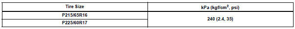
(b) Make sure that the ignition switch is off.
(c) Connect the intelligent tester to the DLC3.
(d) Turn the ignition switch to the ON position.
(e) Display the "TIREPRESS" data for each wheel using the intelligent tester.
(f) Rapidly reduce the tire pressure for each wheel at least 40 kPa (0.41 kg/cm2, 5.8 psi) within 30 seconds.
(g) Check the DATA LIST.
TIRE PRESSURE: 
HINT: *: It may take about 5 to 6 minutes until the values are displayed. If the values are not displayed after a few minutes, perform troubleshooting according to the inspection procedure for DTCs C2121/21 to C2124/24 (See page TW-42).
(h) When the "TIREPRESS" data (ID1 to ID4) has changed, repeat this procedure to identify the tire pressure warning valve and transmitter that corresponds to a DTC.
(i) When all of the "TIREPRESS" data (ID1 to ID4) have changed, identify the malfunctioning tire pressure warning valve and transmitter based on the recorded ID numbers and output DTC.
Result 
NOTICE:
- It may take about 5 to 6 minutes to display the updated data.
- When no "TIREPRESS" data has changed, reset the tire pressure to the appropriate specified value and rotate the tire 90 to 270 degrees. Then forcibly transmit the transmitter ID and recheck it.
- Record the transmitter ID and position that is normal condition.

3 REPLACE TIRE PRESSURE WARNING VALVE AND TRANSMITTER
(a) Replace the identified tire pressure warning valve and transmitter with a new one (See page TW-84).
HINT:
- Before installing a new tire pressure warning valve and transmitter, read and write down its transmitter ID.
- The IDs for the tire pressure warning valve and transmitter which are not replaced should be checked using the tester and recorded.

4 CHECK REGISTRATION OF TRANSMITTER ID
(a) Register the transmitter ID for 4 tires (See page TW-20).

5 PERFORM INITIALIZATION
(a) Perform initialization (See page TW-23).

6 READ VALUE ON INTELLIGENT TESTER
(a) Make sure that the ignition switch is off.
(b) Connect the intelligent tester to the DLC3.
(c) Turn the ignition switch to the ON position.
(d) Select "TIREPRESS" by following the prompts displayed on the intelligent tester.
TIRE PRESSURE:


HINT: *: It may take about 5 to 6 minutes until the values are displayed. If the values are not displayed after a few minutes, perform troubleshooting according to the inspection procedure for DTCs C2121/21 to C2124/24 (See page TW-42).
Result


REPLACE TIRE PRESSURE WARNING ECU (See page TW-87)
 Transmitter ID1 Error
DESCRIPTION
The tire pressure warning valve and transmitters that are installed in the
tire and wheel assemblies
measure the air pressure of the tires. The measured values are transmitted to
...
 Transmitter ID not Registered
DTC C2171/71 Transmitter ID not Registered
DESCRIPTION
The IDs of each tire pressure warning valve and transmitters are registered
to the tire pressure warning
ECU.
When the IDs have never bee ...
Other materials:
Checking monitor status
The purpose of the monitor result (mode 06) is to allow
access to the results for on-board diagnostic monitoring tests
of specific components/systems that are not continuously
monitored. Examples are catalyst, evaporative emission
(EVAP) and thermostat.
The monitor result allows the OBD II sc ...
Radio Receiver Power Source Circuit
DESCRIPTION
This circuit provides power to the radio receiver.
WIRING DIAGRAM
INSPECTION PROCEDURE
1 INSPECT RADIO RECEIVER ASSEMBLY
Disconnect the radio receiver connector.
Measure the resistance according to the value in the
table below.
Standard resistance
Measure t ...
Reassembly
1. INSTALL LH REAR BUMPER SIDE RETAINER
Install the LH rear bumper side retainer with the 3
screws.
2. INSTALL RH REAR BUMPER SIDE RETAINER
Install the RH rear bumper side retainer with the 3
screws.
3. INSTALL REAR BUMPER REINFORCEMENT SUBASSEMBLY
Install the rear bumper reinf ...
