Toyota Sienna Service Manual: ACIS Control Circuit
DESCRIPTION
This circuit opens and closes the Intake Air Control Valve (IACV) in response to changes in the engine load in order to increase the intake efficiency (ACIS: Acoustic Control Induction System).
When the engine speed is between 0 and 4450 rpm and the throttle valve opening angle is 60° or more, the ECM supplies current to the VSV (ON status), to close the IACV. Under other conditions, the VSV is usually OFF and the IACV is open.

WIRING DIAGRAM

INSPECTION PROCEDURE
1 PERFORM ACTIVE TEST BY INTELLIGENT TESTER (OPERATE VSV FOR ACIS)
(a) Connect the intelligent tester to the DLC3.
(b) Start the engine and turn the intelligent tester on.
(c) Select the following menu items: DIAGNOSIS / ENHANCED OBD II / ACTIVE TEST / INTAKE CTL VSV1. Operate the VSV for AICS.
OK: Operational noise can be heard.


2 CHECK INTAKE AIR CONTROL VALVE (OPERATION)
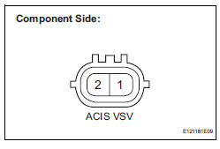
(a) Disconnect the V14 VSV for ACIS connector.
(b) Apply battery voltage between the terminals of the air intake valve connector.
(c) Check the air intake valve operation.
OK: Operational noise can be heard.
(d) Reconnect the VSV for ACIS connector.

3 CHECK HARNESS AND CONNECTOR (VSV FOR ACIS - ECM)

(a) Check the wire harness and connectors between the VSV for ACIS and ECM.
(1) Disconnect the V14 VSV for ACIS connector.
(2) Disconnect the E9 ECM connector.
(3) Measure the resistance according to the value(s) in the table below.
Standard resistance :
(4) Reconnect the VSV for ACIS connector.
(5) Reconnect the ECM connector.


4 INSPECT FUSE (EFI NO. 2 FUSE)

(a) Check the EFI No. 2 fuse.
(1) Remove the EFI No. 2 fuse from the engine room junction block.
(2) Measure the EFI No. 2 fuse resistance.
Standard resistance: Below 1 Ω
(3) Reinstall the EFI No. 2 fuse.


5 CHECK HARNESS AND CONNECTOR (VSV FOR ACIS - EFI RELAY)
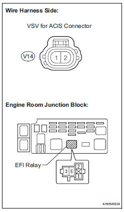
(a) Check the wire harness between the VSV for ACIS connector and EFI relay.
(1) Remove the EFI relay from the engine room junction block.
(2) Disconnect the V14 VSV connector.
(3) Measure the resistance according to the value(s) in the table below.
Standard resistance :
(4) Reinstall the EFI relay.
(5) Reconnect the VSV connector.


CHECK ECM POWER SOURCE CIRCUIT (See page ES-437)
 Cranking Holding Function Circuit
DESCRIPTION
The system detects the ignition switch's starting signal (STSW) and then
supplies current to the starter
until the ECM judges that the engine has started successfully. The purpose is t ...
 Air Intake Control Circuit
DESCRIPTION
The air cleaner is equipped with two inlets, one of which is opened or closed
by the Air Intake Control
Valve (AICV). This system reduces intake noise and increases engine power at
l ...
Other materials:
Throttle Actuator Control Motor Current Range / Performance
DESCRIPTION
The ETCS (Electronic Throttle Control System) has a dedicated power supply
circuit. The voltage (+BM)
is monitored and when it is low (less than 4 V), the ECM determines that there
is a malfunction in the
ETCS and cuts off the current to the throttle actuator.
When the volt ...
On-vehicle cleaning
1. INSPECT RADIATOR ASSEMBLY
(a) Check that the radiator and condenser are not
blocked with leaves, dirt, or insects. Clean the hose
connections.
If the fins are blocked, wash them with water or a
steam cleaner.
NOTICE:
If the distance between the steam cleaner and
core is ...
Terminals of ECU
1. RADIO AND NAVIGATION ASSEMBLY
*1: with Rear Seat Entertainment System
Reference: waveform 1
HINT:
Terminal: VV+ - VV-
Gauge set: 200 mV/DIV, 10 μs/DIV
Condition: DVD is played on radio and navigation
assembly
Reference: wave ...
