Toyota Sienna Service Manual: Center Airbag Sensor Assembly Malfunction
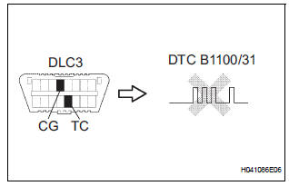
DTC B1100/31 Center Airbag Sensor Assembly Malfunction
DESCRIPTION
The center airbag sensor assembly consists of the center airbag sensor assembly, safing sensor, drive circuit, diagnosis circuit and ignition control, etc.
It receives signals from the airbag sensor, judges whether or not the SRS must be activated, and detects diagnosis system malfunction.
DTC B1100/31 is recorded when a malfunction is detected in the center airbag sensor assembly circuit.
|
DTC No. |
DTC Detecting Condition |
Trouble Area |
|
B1100/31 |
|
|
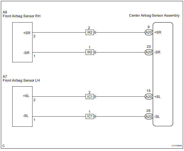
WIRING DIAGRAM
INSPECTION PROCEDURE
HINT: When a trouble code is displayed simultaneously with B1100/31, repair the malfunction indicated by this code (except B1100/31) first.
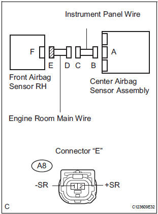
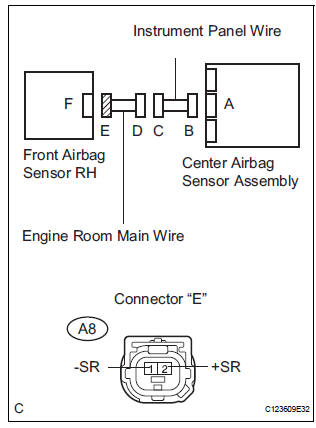
1 CHECK FRONT AIRBAG SENSOR RH CIRCUIT (SHORT TO GROUND)
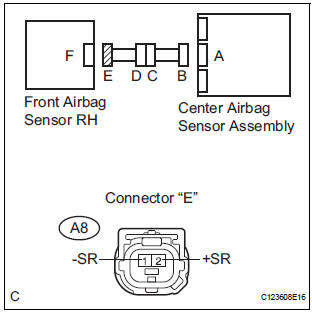
- Turn the ignition switch to the LOCK position.
- Disconnect the negative (-) terminal cable from the battery, and wait for at least 90 seconds.
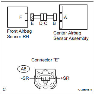
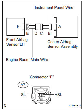
- Disconnect the connectors from the front airbag sensor RH and the center airbag sensor assembly.
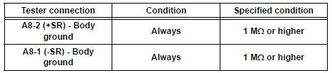
- Measure the resistance according to the value(s) in the table below.
Standard resistance
 Go to step 8

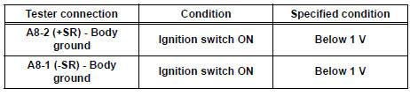
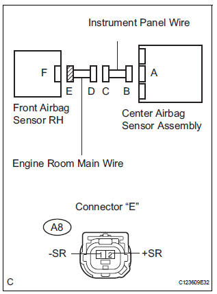
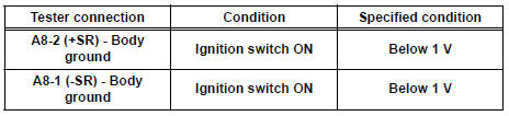
2 CHECK FRONT AIRBAG SENSOR RH CIRCUIT (SHORT TO B+)
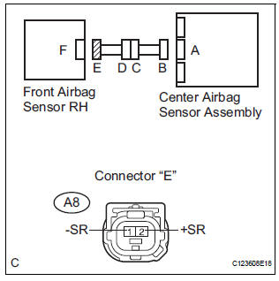
- Connect the negative (-) terminal cable to the battery, and wait for at least 2 seconds.
- Turn the ignition switch to the ON position.
- Measure the voltage according to the value(s) in the table below.
Standard voltage
 Go to step 9

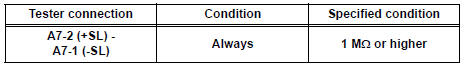
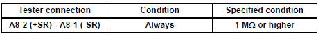
3 CHECK FRONT AIRBAG SENSOR RH CIRCUIT (SHORT)
- Turn the ignition switch to the LOCK position.
- Disconnect the negative (-) terminal cable from the battery, and wait for at least 90 seconds.
- Measure the resistance according to the value(s) in the table below.
Standard resistance
 Go to step 10

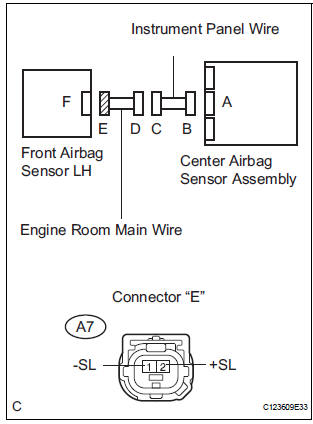
4 CHECK FRONT AIRBAG SENSOR LH CIRCUIT (SHORT TO GROUND)
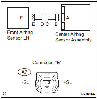
- Disconnect the connector from the front airbag sensor LH.
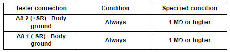
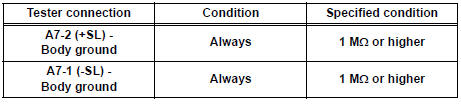
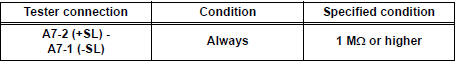
- Measure the resistance according to the value(s) in the table below.
Standard resistance
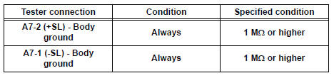
Go to step 11

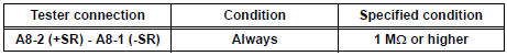
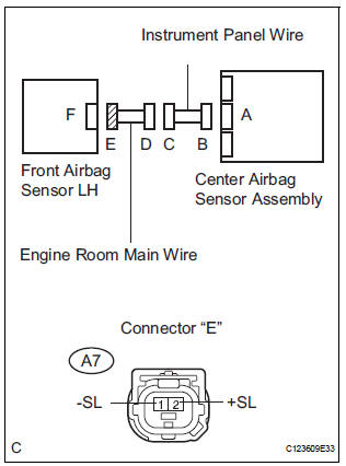
5 CHECK FRONT AIRBAG SENSOR LH CIRCUIT (SHORT TO B+)
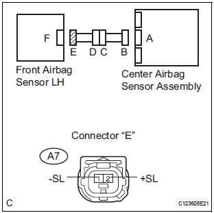
- Connect the negative (-) terminal cable to the battery, and wait for at least 2 seconds.
- Turn the ignition switch to the ON position.
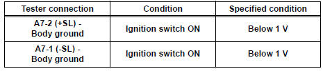
- Measure the voltage according to the value(s) in the table below.
Standard voltage
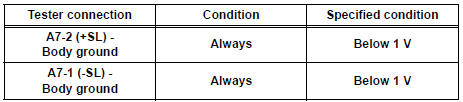
 Go to step 12

6 CHECK FRONT AIRBAG SENSOR LH CIRCUIT (SHORT)
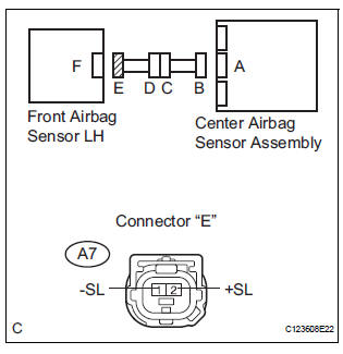
- Turn the ignition switch to the LOCK position.
- Disconnect the negative (-) terminal cable from the battery, and wait for at least 90 seconds.
- Measure the resistance according to the value(s) in the table below.
Standard resistance
 Go to step 13

7 CHECK CENTER AIRBAG SENSOR ASSEMBLY
- Connect the connectors to the center airbag sensor assembly, front airbag sensors RH and LH.
- Connect the negative (-) terminal cable to the battery, and wait for at least 2 seconds.
- Turn the ignition switch to the ON position, and wait for at least 60 seconds.
- Clear the DTCs stored in memory (5).
- Turn the ignition switch to the LOCK position.
- Turn the ignition switch to the ON position, and wait for at least 60 seconds.
- Check the DTCs (5).
OK: DTC B1100/31 is not output.
 REPLACE CENTER AIRBAG SENSOR
ASSEMBLY
REPLACE CENTER AIRBAG SENSOR
ASSEMBLY

USE SIMULATION METHOD TO CHECK
8 CHECK ENGINE ROOM MAIN WIRE (SHORT TO GROUND)
- Disconnect the engine room main wire connector from the instrument panel wire.
- Measure the resistance according to the value(s) in the table below.
Standard resistance
 REPAIR OR REPLACE ENGINE ROOM
MAIN
WIRE
REPAIR OR REPLACE ENGINE ROOM
MAIN
WIRE

REPAIR OR REPLACE INSTRUMENT PANEL WIRE
9 CHECK ENGINE ROOM MAIN WIRE (SHORT TO B+)
- Turn the ignition switch to the LOCK position.
- Disconnect the negative (-) terminal cable from the battery, and wait for at least 90 seconds.
- Disconnect the engine room main wire connector from the instrument panel wire.
- Connect the negative (-) terminal cable to the battery, and wait for at least 2 seconds.
- Turn the ignition switch to the ON position.
- Measure the voltage according to the value(s) in the table below.
Standard voltage
 REPAIR OR REPLACE ENGINE
ROOM MAIN
WIRE
REPAIR OR REPLACE ENGINE
ROOM MAIN
WIRE

REPAIR OR REPLACE INSTRUMENT PANEL WIRE
10 CHECK ENGINE ROOM MAIN WIRE (SHORT)
- Disconnect the engine room main wire connector from the instrument panel wire.
- Measure the resistance according to the value(s) in the table below.
Standard resistance
 REPAIR OR REPLACE ENGINE ROOM
MAIN
WIRE
REPAIR OR REPLACE ENGINE ROOM
MAIN
WIRE

REPAIR OR REPLACE INSTRUMENT PANEL WIRE
11 CHECK ENGINE ROOM MAIN WIRE (SHORT TO GROUND)
- Disconnect the engine room main wire connector from the instrument panel wire.
- Measure the resistance according to the value(s) in the table below.
Standard resistance
 REPAIR OR REPLACE ENGINE ROOM
MAIN
WIRE
REPAIR OR REPLACE ENGINE ROOM
MAIN
WIRE

REPAIR OR REPLACE INSTRUMENT PANEL WIRE
12 CHECK ENGINE ROOM MAIN WIRE (SHORT TO B+)
- Turn the ignition switch to the LOCK position.
- Disconnect the negative (-) terminal cable from the battery, and wait for at least 90 seconds.
- Disconnect the engine room main wire connector from the instrument panel wire.
- Connect the negative (-) terminal cable to the battery, and wait for at least 2 seconds.
- Turn the ignition switch to the ON position.
- Measure the voltage according to the value(s) in the table below.
Standard voltage
 REPAIR OR REPLACE ENGINE ROOM
MAIN
WIRE
REPAIR OR REPLACE ENGINE ROOM
MAIN
WIRE

REPAIR OR REPLACE INSTRUMENT PANEL WIRE
13 CHECK ENGINE ROOM MAIN WIRE (SHORT)
- Disconnect the engine room main wire connector from the instrument panel wire.
- Measure the resistance according to the value(s) in the table below.
Standard resistance
 REPAIR OR REPLACE ENGINE
ROOM MAIN
WIRE
REPAIR OR REPLACE ENGINE
ROOM MAIN
WIRE

REPAIR OR REPLACE INSTRUMENT PANEL WIRE
 Short to B+ in Front Pretensioner Squib LH Circuit
DTC B0138/72 Short to B+ in Front Pretensioner Squib LH Circuit
DESCRIPTION
The front pretensioner squib LH circuit consists of the center airbag sensor
assembly and the front seat
outer belt ass ...
 Half Connection in Center Airbag Sensor
Assembly Connectors
Half Connection in Center Airbag Sensor
Assembly Connectors
DTC B1135/24 Half Connection in Center Airbag Sensor
Assembly Connectors
DESCRIPTION
The center airbag sensor assembly connector has a mechanism that electrically
detects half connection.
The ...
Other materials:
Receiving a message
When an e-mail/SMS/MMS is received, the incoming message screen
pops up with sound and is ready to be operated on the screen.
Select to check the message.
Select to refuse the message.
Select to call the message
sender.
Receiving a message
Depending on the cellular phone used f ...
Yaw rate sensor check (when using sst check wire)
(a) Check the zero point voltage of the yaw rate sensor.
(1) Keep the vehicle in a stationary condition on a
level surface for 1 second or more.
(b) Check the output of the yaw rate sensor.
(1) Move the shift lever to the D position, drive the
vehicle at a speed of approximately 3 mph (5
...
Installation
1. INSTALL REAR SEAT 3 POINT TYPE BELT
ASSEMBLY (for 8-Passenger)
HINT: Refer to the instructions for reassembly of the rear
No. 1 seat assembly (for center seat).
Install the rear seat 3 point type belt assembly with
the bolt.
Torque: 42 N*m (430 kgf*cm, 31 ft.*lbf)
2. INSTALL ...
