Toyota Sienna Service Manual: Disassembly
1. REMOVE FRONT DIFFERENTIAL RING GEAR

(a) Place the match-marks on the ring gear and differential case.

(b) Remove the 16 bolts.

(c) Using a plastic hammer, tap ring gear to remove it from the case.
2. REMOVE FRONT DIFFERENTIAL SIDE GEAR

(a) Remove the differential LH case from the differential case assembly.
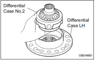
(b) Remove the differential case No.2 from the differential case LH.

(c) Remove the front differential side gear, front differential side gear thrust washer, conical spring and center differential side gear thrust washer No.2 from the differential case LH.

(d) Using a snap ring expander, remove the pinion shaft spacer snap ring.

(e) Using a pin punch and hammer, remove 3 straight pins.

(f) Remove the center differential pinion shaft and 2 differential pinion shafts.

(g) Remove 4 front differential pinions, 4 front differential pinion thrust washers, front differential pinion shaft holder, front differential planetary ring and differential side gear thrust washer No.1.
3. REMOVE FRONT DIFFERENTIAL CASE REAR TAPERED ROLLER BEARING

(a) Using SST, remove the front differential case rear tapered roller bearing from the differential case.
SST 09950-00020, 09950-00030, 09950-60010 (09951-00480)

(b) Using SST, remove the front differential case rear tapered roller bearing outer race and differential case washer
SST 09308-00010
4. REMOVE CENTER DIFFERENTIAL PINION

(a) Using torx socket (T50), remove the 15 bolts.

(b) Place the matchmarks on the differential intermediate case and differential case.
(c) Remove the differential intermediate case from the differential case RH.

(d) Remove the center differential side gear, conical spring washer and center differential side gear thrust washer No.1 RH from the differential case RH.

(e) Remove the differential spider, 5 center differential pinions and 5 center differential pinion thrust washers from the differential intermediate case.
5. REMOVE FRONT DIFFERENTIAL CASE FRONT TAPERED ROLLER BEARING

(a) Using SST, remove the front differential case front tapered roller bearing from the differential case.
SST 09950-00020, 09950-00030 SST 09950-60010 (09951-00600)

(b) Using SST, remove the front differential case front tapered roller bearing outer race and differential case washer.
SST 09308-00010
6. REMOVE TRANSAXLE HOUSING OIL SEAL

(a) Using SST, remove the oil seal.
SST 09950-70010 (09951-07100) SST 09649-17010
7. REMOVE DIFFERENTIAL SIDE BEARING RETAINER OIL SEAL

(a) Using SST, remove the oil seal.
SST 09950-70010 (09951-07100), 09608-10010
 Differential case
COMPONENTS
...
 Inspection
1. INSPECT FRONT DIFFERENTIAL
(a) Using a dial indicator, measure the backlash of one
pinion gear while holding the front differential side
gear toward the case.
Standard backlash:
0.05 - 0.2 ...
Other materials:
Front Speed Sensor RH Circuit
DESCRIPTION
The speed sensor detects wheel speed and transmits the appropriate signals to
the ECU. These signals
are used for control of the ABS control system. The front and rear rotors have
48 serrations each.
When the rotors rotate, the magnetic field generated by the permanent magne ...
Tire Pressure Warning Reset Switch Circuit
DESCRIPTION
The ECU enters the initialization mode and performs initialization
automatically, when the tire pressure
warning ECU receives the signal from the tire pressure warning reset switch. If
the ECU receives the
signal, the tire pressure warning light blinks 3 times (1 second on, 1 seco ...
Short in Driver Side Squib Circuit
DTC B0100/13 Short in Driver Side Squib Circuit
DESCRIPTION
The driver side squib circuit consists of the center airbag sensor assembly,
the spiral cable and the
steering pad. The circuit instructs the SRS to deploy when deployment conditions
are met. DTC B0100/13
is recorded when a short ci ...
