Toyota Sienna Service Manual: Disassembly
1. SEPARATE REAR DRIVE SHAFT INBOARD JOINT BOOT CLAMP
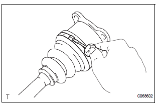
(a) Using a screwdriver, remove the 2 rear drive shaft inboard joint boot clamps as shown in the illustration.
2. SEPARATE REAR DRIVE SHAFT INBOARD JOINT BOOT
(a) Separate the rear drive shaft inboard joint boot from the inboard joint assembly.
3. REMOVE REAR DRIVE SHAFT INBOARD JOINT ASSEMBLY

(a) Put matchmarks on the inboard joint assembly and outboard joint shaft.
NOTICE: Do not use a punch for the marks.
(b) Pull out the inboard joint assembly.
NOTICE: Be careful not to drop the balls.

(c) Place matchmarks on the outboard joint shaft, inner race and cage.
NOTICE: Do not punch the marks.
(d) Remove the 6 bolts.
(e) Slide the cage toward outboard joint.

(f) Using a snap ring expander, remove the snap ring.

(g) Using a brass bar and hammer, remove the inner race.
(h) Remove the cage.
(i) Remove the inboard joint boot, inboard joint boot clamp and inboard joint boot No. 2 clamp.
4. REMOVE REAR DRIVE SHAFT OUTBOARD JOINT BOOT CLAMP

(a) Using pliers, remove the 2 rear drive shaft outboard joint boot clamps as shown in the illustration.
5. REMOVE REAR DRIVE SHAFT OUTBOARD JOINT BOOT
(a) Remove the outboard joint boot from the outboard joint shaft.
(b) Remove the old grease from the outboard joint.
NOTICE: Do not disassemble the outboard joint.
 Removal
1. REMOVE REAR WHEEL
2. REMOVE TAIL EXHAUST PIPE ASSEMBLY (See page
EX-8)
3. SEPARATE REAR SPEED SENSOR
(a) Remove the bolt and the speed sensor from the
axle carrier.
NOTICE:
Be careful not ...
 Inspection
1. INSPECT REAR DRIVE SHAFT ASSEMBLY LH
(a) Check that there is no remarkable play in the radial
direction of the outboard joint.
(b) Check that the inboard joint slides smoothly in the
thru ...
Other materials:
VSC Warning Light does not Come ON
DESCRIPTION
The skid control ECU is connected to the combination meter via CAN and
multiplex communications.
If the skid control ECU stores DTCs to shut down TRAC and VSC operation, the VSC
warning light comes
on in the combination meter.
WIRING DIAGRAM
Refer to VSC Warning Light Remains ...
Short to GND in Side Squib LH Circuit
DTC B0117/45 Short to GND in Side Squib LH Circuit
DESCRIPTION
The side squib LH circuit consists of the center airbag sensor assembly and
the front seat side airbag
assembly LH.
This circuit instructs the SRS to deploy when deployment conditions are met.
DTC B0117/45 is recorded when a s ...
Terminals of ECU
1. POSITION CONTROL ECU AND SWITCH ASSEMBLY
(POWER SEAT CONTROL SWITCH AND ECU)
Disconnect the P58 and P59 connectors.
Check the voltage of each terminal of the wire
harness side connectors.
If the result is not as specified, there may be a
malfunction in the wire harn ...
