Toyota Sienna Service Manual: DRL Relay Circuit
DESCRIPTION
The Multiplex network body ECU controls the DRL No.2 relay
WIRING DIAGRAM

INSPECTION PROCEDURE
1 PERFORM ACTIVE TEST BY INTELLIGENT TESTER
- Connect the intelligent tester to DLC3.
- Turn the ignition switch ON and push the intelligent tester main switch ON.
- Select the item below in the ACTIVE TEST and then check that the relay operates.
BODY NO.1:

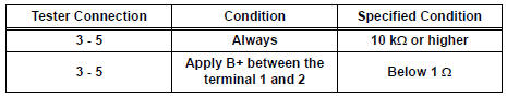
2 INSPECT DRL NO.2 RELAY

- Inspect DRL No.2 Relay continuity.
Resistance
3 CHECK HARNESS AND CONNECTOR (POWER SOURCE)

- Disconnect the connector from the instrument panel junction block assembly.
- Measure the voltage according to the value(s) in the table below.
Voltage

4 INSPECT INSTRUMENT PANEL JUNCTION BLOCK ASSEMBLY
- Reconnect the connector to the instrument panel junction block assembly.

- Measure the voltage according to the value(s) in the table below.
Voltage


5 INSPECT RELAY (DRL NO.3, DRL NO.4)

- Inspect DRL NO.4 Relay continuity.
Resistance

- Inspect DRL NO.3 Relay continuity.

Resistance

6 INSPECT DAYTIME RUNNING LIGHT RESISTER

- Measure the resistance according to the value(s) in the table below.
Resistance

REPAIR OR REPLACE HARNESS OR CONNECTOR
 Headlight Relay Circuit
DESCRIPTION
The Multiplex network body ECU controls HEAD relay when signal is received
from headlight dimmer
switch assembly.
WIRING DIAGRAM
INSPECTION PROCEDURE
1 PERFORM ACTIVE TEST BY IN ...
 Front Fog Light Circuit
DESCRIPTION
The Multiplex network body ECU controls FOG relay when signal is received
from headlight dimmer
switch assembly.
WIRING DIAGRAM
INSPECTION PROCEDURE
1 PERFORM ACTIVE TEST BY INT ...
Other materials:
Idle Control System Malfunction
DTC P0505 Idle Control System Malfunction
DESCRIPTION
The idling speed is controlled by the ETCS (Electronic Throttle Control
System). The ETCS is comprised
of: 1) the one valve type throttle body; 2) the throttle actuator, which
operates the throttle valve; 3) the
Throttle Position (TP) sen ...
Camshaft Position "B" - Timing Over-Advanced
DTC P0014 Camshaft Position "B" - Timing Over-Advanced
or System Performance (Bank 1)
DTC P0015 Camshaft Position "B" - Timing Over-Retarded
(Bank 1)
DTC P0024 Camshaft Position "B" - Timing Over-Advanced
or System Performance (Bank 2)
DTC P0025 Camshaft Position ...
Engine Coolant Temperature / Intake Air Temperature Correlation
DESCRIPTION
The ECM calculates the difference between the readings of the coolant
temperature sensor and intake air
temperature sensor. If the difference is greater than 20°C (68°F), the ECM will
judge this as a malfunction
and will set this DTC.
HINT:
Waiting is required t ...