Toyota Sienna Service Manual: Dtc check / clear
1. DTC CHECK/CLEAR (WHEN USING INTELLIGENT TESTER):

(a) DTC check
(1) Connect the intelligent tester to the DLC3.
(2) Turn the ignition switch to the ON position.
(3) Read the DTCs following the prompts on the tester screen.
(b) DTC clear
(1) Connect the intelligent tester to the DLC3.
(2) Turn the ignition switch to the ON position.
(3) Operate the intelligent tester to clear the codes.
HINT: Refer to the intelligent tester operator's manual for further details.
2. DTC CHECK/CLEAR (WHEN USING SST CHECK WIRE):

(a) DTC check
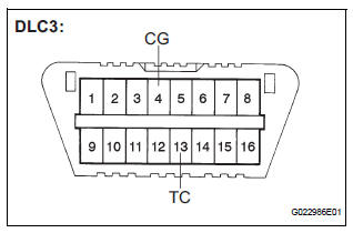
(1) Using SST, connect terminals TC and CG of the DLC3.
SST 09843-18040
(2) Turn the ignition switch to the ON position.
(3) Read DTC from the ABS and VSC warning lights on the combination meter.
HINT:
If no code appears, inspect the TC and CG
terminal circuit, and ABS and VSC warning light
circuits. 
(4) As an example, the illustration below shows the blinking patterns of the normal system code and trouble codes 11 and 21.

(5) Codes are explained in the code table (See page BC-88).
(6) After completing the check, disconnect terminals TC and CG of the DLC3, and turn off the display.
If 2 or more DTCs are detected at the same time, the DTCs will be displayed in ascending order.
(b) DTC clear
(1) Using SST, connect terminals TC and CG of the DLC3.
SST 09843-18040 (2) Turn the ignition switch to the ON position.

(3) Clear the DTCs stored in the ECU by depressing the brake pedal 8 times or more within 5 seconds.
(4) Check that the warning light indicates the normal system code.
(5) Remove the SST from the terminals of the DLC3.
HINT: Clearing the DTCs cannot be performed by removing the battery cable or the ECU-IG fuse.
3. END OF DTC CHECK/CLEAR:
(a) Turn the ignition switch to the ON position.
(b) Check that the ABS and VSC warning lights go off within approximately 3 seconds.
 Terminals of ecu
1. Terminal of ECU
(*1): Models with dynamic laser cruise control
(*2): 2WD model
2. Terminal Inspection
(a) Disconnect the connector and measure the voltage
or resistance on the wire harness ...
 Freeze frame data
1. FREEZE FRAME DATA
(a) The vehicle (sensor) status, stored during ABS and/
or VSC operation or at the time of an error code
detection, can be displayed by the intelligent tester.
(b) Only one ...
Other materials:
DSP Error/ DSP Error
DTC 62-78 DSP Error
DTC 63-78 DSP Error
DESCRIPTION
INSPECTION PROCEDURE
HINT:
After the inspection is completed, clear the DTCs.
NOTICE:
These codes may be output even if there is no malfunction.
If these codes are output frequently, replace the radio receiver.
1 CLEA ...
Data list / active test
1. DATA LIST
HINT:
Using the DATA LIST displayed on the intelligent tester,
you can read the value of the switch, sensor, actuator,
etc. without parts removal. Reading the DATA LIST as
the first step of troubleshooting is one way to shorten the
labor time.
Connect the intelligent tester to ...
Open in Front Passenger Side Squib Circuit
DTC B0106/54 Open in Front Passenger Side Squib Circuit
DESCRIPTION
The front passenger side squib circuit consists of the center airbag sensor
assembly and the front
passenger airbag assembly.
The circuit instructs the SRS to deploy when deployment conditions are met.
DTC B0106/54 is rec ...
