Toyota Sienna Service Manual: DTC check / clear
1. DTC CHECK (USING SST CHECK WIRE)
- Check the DTCs (Present trouble code).
- Turn the ignition switch ON, and wait for approximately 60 seconds.
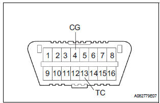
- Using SST, connect terminals TC and CG of the DLC3.
SST 09843-18040
NOTICE: Connect the terminals to the correct positions to avoid a malfunction.
- Check the DTCs (Past trouble code).
- Using SST, connect terminals TC and CG of the
DLC3.
SST 09843-18040
NOTICE: Connect the terminals to the correct positions to avoid a malfunction. - Turn the ignition switch ON, and wait for approximately 60 seconds.
- Read the DTCs.
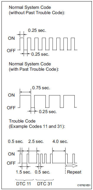
- Read the blinking patterns of the DTCs. As examples, the blinking patterns for the normal system code and trouble codes 11 and 31 are shown in the illustration.
- Normal system code indication (w/o past trouble code)
- he light blinks twice per second.
- Normal system code indication (w/ past trouble code)
- hen the past trouble code is stored in the center airbag sensor assembly, the light blinks only once per second.
- Trouble code indication
The first two blinkings indicate the first DTC.
The second blinking occurs after a 1.5- second pause.
If there are more than 1 code, there will be a 2.5- second pause between each code. After all codes are shown, there will be a 4.0-second pause, and they all will be repeated.
HINT:
- If 2 or more malfunctions are found, the indication begins with the smaller numbered code.
- If DTCs are indicated without connecting the terminals, proceed to the "Diagnosis Circuit"
2. DTC CLEAR (USING SST CHECK WIRE)
- Clear the DTCs.
- When the ignition switch is turned off, the DTCs
are cleared.
HINT: Depending on the DTC, the code may not be cleared by turning off the ignition switch. In this case, proceed to the next procedure.
- Using SST, connect terminals TC and CG of the
DLC3, and then turn the ignition switch to the
ON position.
SST 09843-18040
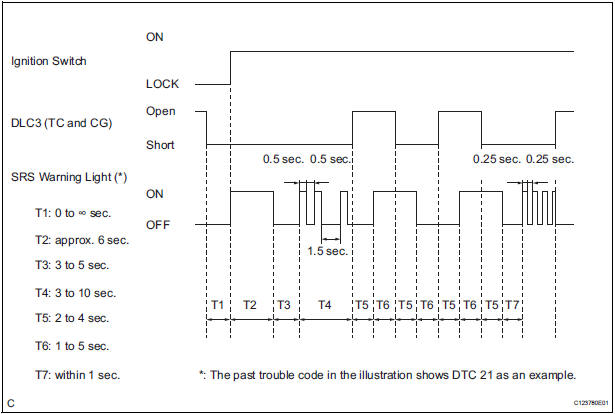
- Disconnect terminal TC of the DLC3 within 3 to 10 seconds after the DTCs are output, and check if the SRS warning light comes on after 3 seconds.
- ) Within 2 to 4 seconds after the SRS warning light comes on, connect terminals TC and CG of the DLC3.
- ) The SRS warning light should go off within 2 to 4 seconds after connecting terminals TC and CG of the DLC3. Then, disconnect terminal TC within 2 to 4 seconds after the SRS warning light goes off.
- The SRS warning light comes on again within 2
to 4 seconds after disconnecting terminal TC.
Then, reconnect terminals TC and CG of the DLC3 within 2 to 4 seconds after the SRS warning light comes on.
- Check if the SRS warning light goes off within 2
to 4 seconds after connecting terminals TC and
CG of the DLC3. Also check if the normal
system code is output within 1 second after the
SRS warning light goes off.
If DTCs are not cleared, repeat this procedure until the codes are cleared.
3. DTC CHECK
- Check the DTCs.
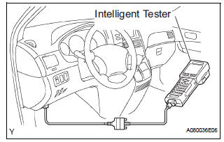
- Connect the intelligent tester to the DLC3.
- Turn the ignition switch to the ON position.
- Check the DTCs by following the prompts on the
tester screen.
HINT: Refer to the intelligent tester operator's manual for further details.
- Clear the DTCs.
- Connect the intelligent tester to the DLC3.
- Turn the ignition switch to the ON position.
- Clear the DTCs by following the prompts on the
tester screen.
HINT: Refer to the intelligent tester operator's manual for further details.
 Diagnosis system
1. CHECK DLC3
The ECU uses ISO 15765-4 for communication.
The terminal arrangement of the DLC3 complies
with SAE J1962 and matches the ISO 15765-4
format.
NOTICE:
*: Before ...
 Check mode procedure
1. CHECK MODE (SIGNAL CHECK): DTC CHECK
Connect the intelligent tester to the DLC3.
) Turn the ignition switch to the ON position.
) Select the "SIGNAL CHECK", and proceed
...
Other materials:
Sensor signal check by test mode (signal check) (when using intelligent
tester)
(a) When having replaced the skid control ECU and/or
yaw rate and deceleration sensor, perform zero
point calibration of the yaw rate and deceleration
sensor.
HINT:
If the ignition switch is turned from the ON
position to the ACC or off during test mode
(signal check), DTCs of the signal ...
Installation
1. INSTALL ENGINE OIL COOLER
(a) Clean the oil cooler contact surface on the cooler
mounting.
(b) Install a new O-ring to the oil cooler.
(c) Install the oil cooler assembly with the union bolt.
Torque: 68 N*m (693 kgf*cm, 50 ft.*lbf)
Install the 2 water by-pass hoses with the bolt ...
Installation
1. INSTALL RACK & PINION POWER STEERING GEAR ASSEMBLY
(a) Install the power steering gear assembly with the 2
bolts and nuts.
Torque: 70 N*m (714 kgf*cm, 52 ft.*lbf)
2. CONNECT PRESSURE FEED TUBE ASSEMBLY
(a) Connect the pressure feed tube assembly to the
power steering gear asse ...
