Toyota Sienna Service Manual: Dtc check / clear
| Notice: All the stored dtcs and freeze frame data are erased if: 1) the ecm is changed from normal mode to check mode or vice versa; or 2) the ignition switch is turned from on to acc or off while in check mode. Before changing modes, always check and make a note of any dtcs and freeze frame data. |
HINT:
- Dtcs which are stored in the ecm can be displayed on an intelligent tester. An intelligent tester can display current and pending dtcs.
- Some DTCs are not set if the ECM does not detect the same malfunction again during the second consecutive driving cycle. However, such malfunctions, detected on only one occasion, are stored as pending DTCs.
1. Check dtc (using an intelligent tester)
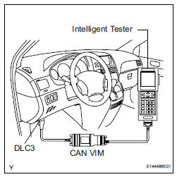
(a) Connect the intelligent tester to the DLC3.
(b) Turn the ignition switch to the ON position.
(c) Turn the tester ON.
(d) Select the following menu items: DIAGNOSIS / ENHANCED OBD II / DTC INFO / CURRENT CODES.
(e) Check for the DTC(s) and freeze frame data, and then write them down.
(f) Check the details of the DTC(s) (See page ES-56).
2. CLEAR DTC (Using the intelligent tester)
(a) Connect the intelligent tester to the DLC3.
(b) Turn the ignition switch to the ON position.
(c) Turn the tester ON.
(d) Select the following menu items: DIAGNOSIS / ENHANCED OBD II / DTC INFO / CLEAR CODES.
(e) Press the YES button.
3. CLEAR DTC (Without using an intelligent tester)
(a) Perform either one of the following operations:
(1) Disconnect the negative battery cable for more than 1 minute.
(2) Remove the EFI No. 1 and ETCS fuses from the Relay Block (R/B) located inside the engine compartment for more than 1 minute.
 Diagnosis system
DESCRIPTION
(a) When troubleshooting OBD II (On-Board
Diagnostics) vehicles, an intelligent tester
(complying with SAE J1987) must be connected to
the DLC3 (Data Link Connector 3) of the vehicle.
...
 Freeze frame data
1. DESCRIPTION
(a) The ECM records vehicle and driving condition
information as freeze frame data the moment a DTC
is stored. When troubleshooting, freeze frame data
can be helpful in determining ...
Other materials:
Cooling fan ecu
ON-VEHICLE INSPECTION
1. INSPECT COOLING FAN ECU
(a) Inspect the input voltage.
(1) Disconnect the cooling fan ECU connector.
(2) Turn the ignition switch to the ON position.
Check the voltage of the +B terminal of the
disconnected wire harness side connector.
Standard voltage:
9 t ...
Installation
1. INSTALL TRANSFER ASSEMBLY
(a) Apply sealant 1281 to the transaxle assembly and
transfer assembly in continuous beaded from of 1.2
mm diameter as shown in the illustration.
NOTICE:
Wipe any grease off from the attaching
surfaces.
Install it within 10 minutes after applying the
se ...
Removal
1. DISCONNECT CABLE FROM NEGATIVE BATTERY
TERMINAL
2. REMOVE REAR NO. 2 SEAT LEG SIDE GARNISH SUB-ASSEMBLY
Disengage the 9 clips and remove the rear No. 2
seat leg side garnish sub-assembly.
Remove the 9 clips from the rear No. 2 seat leg side
garnish sub-assembly.
3. ...
