Toyota Sienna Service Manual: ECU Power Source Circuit
DESCRIPTION
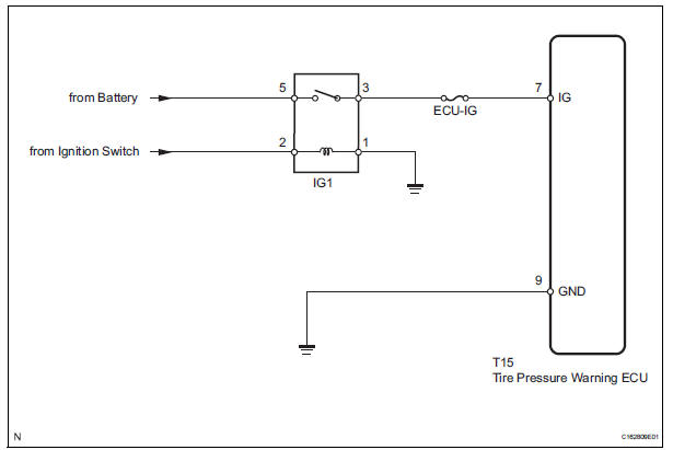
This is the power source for the tire pressure warning ECU.
WIRING DIAGRAM
INSPECTION PROCEDURE
NOTICE: When replacing the tire pressure warning ECU, read the transmitter IDs stored in the old ECU using the intelligent tester and write them down before removal.
It is necessary to register an ID code after replacing the tire pressure warning valve and transmitter and/or the tire pressure warning ECU (See page TW-20).
1 INSPECT FUSE (ECU-IG)
(a) Remove the ECU-IG fuse from the instrument panel junction block.
(b) Measure the resistance of the fuse.
Standard resistance: Below 1 Ω


2 INSPECT IGNITION RELAY NO. 1

(a) Remove the IG1 relay from the instrument panel junction block.
(b) Measure the resistance according to the value(s) in the table below.
Standard resistance 


3 CHECK HARNESS AND CONNECTOR (ECU - BATTERY AND BODY GROUND)

(a) Disconnect the T15 ECU connector.
(b) Measure the voltage according to the value(s) in the table below.
Standard voltage 
(c) Measure the resistance according to the value(s) in the table below.
Standard resistance


PROCEED TO NEXT CIRCUIT INSPECTION SHOWN IN PROBLEM SYMPTOMS TABLE (See page TW-28)
 Tire Pressure Warning Light Circuit
DESCRIPTION
If the ECU detects trouble, the tire pressure warning light blinks (comes on
after blinking for 1 minute) and
tire pressure monitor is cancelled at the same time. At this time, the ECU ...
 TC and CG Terminal Circuit
DESCRIPTION
DTC output mode is set by connecting terminals 13 (TC) and 4 (CG) of the
DLC3. The DTCs are indicated
by blinks of the tire pressure warning light.
WIRING DIAGRAM
HINT:
When eac ...
Other materials:
Enter test mode
HINT:
Operation of the tire pressure warning reset switch
can be checked in TEST MODE.
During TEST MODE, the system is not initialized by
pushing the tire pressure warning reset switch. The
circuit of the tire pressure warning reset switch can be
inspected during this mode.
(a) Make ...
Removal
HINT:
Replace the RH side by the same procedures as the LH side.
1. REMOVE REAR WHEEL
2. REMOVE REAR AXLE SHAFT LH NUT (See page DS-
22)
3. SEPARATE REAR DISC BRAKE CALIPER
ASSEMBLY LH
(a) Removing the 2 bolts, separate the rear disc brake
caliper assembly LH.
4. REMOVE REAR DISC
5. SEPARA ...
Removal
1. REMOVE REAR DOOR SCUFF PLATE
2. REMOVE REAR DOOR WEATHERSTRIP
3. REMOVE BACK DOOR WEATHERSTRIP
4. REMOVE BACK DOOR SCUFF PLATE
5. REMOVE FRONT QUARTER TRIM PANEL ASSEMBLY
Remove the floor anchor cover.
Remove the bolt and disconnect the No. 2 rear seat
outer belt assem ...
