Toyota Sienna Service Manual: Engine rear oil seal
Components

Removal
1. REMOVE AUTOMATIC TRANSAXLE ASSEMBLY (for 2WD)
HINT:
See page AX-163.
2. REMOVE AUTOMATIC TRANSAXLE ASSEMBLY (for 4WD)
HINT: See page AX-167.
3. REMOVE DRIVE PLATE AND RING GEAR SUBASSEMBLY

(a) Using SST, hold the crankshaft.
SST 09213-70011 (09213-70020), 09330-00021

(b) Remove the 8 bolts, front spacer, drive plate and rear spacer.
4. REMOVE ENGINE REAR OIL SEAL

(a) Using a knife, cut off the oil seal lip.
(b) Using a screwdriver, pry out the oil seal.
NOTICE:
Be careful not to damage the crankshaft. Tape the screwdriver tip before use.
INSTALLATION
1. INSTALL ENGINE REAR OIL SEAL
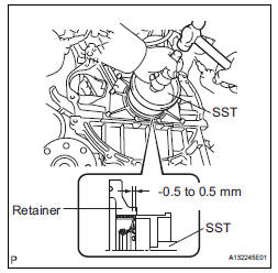
(a) Apply MP grease to a new oil seal lip.
(b) Using SST and a hammer, tap in the oil seal.
SST 09223-15030, 09950-70010 (09951-07150) Oil seal tap in depth: -0.5 to 0.5 mm (-0.020 to 0.020 in.)
2. INSTALL DRIVE PLATE AND RING GEAR SUBASSEMBLY

(a) Using SST, hold the crankshaft.
SST 09213-70011 (09213-70020), 09330-00021

(b) Apply adhesive to 2 or 3 threads of the mounting bolt end.
Adhesive: Part No. 08833-00070, THREE BOND 1324 or equivalent
(1) Install the front spacer, drive plate and rear spacer on the crankshaft.
(2) Install and tighten the 8 mounting bolts uniformly in several steps.
Torque: 83 N*m (850 kgf*cm, 61 ft.*lbf)

3. INSTALL AUTOMATIC TRANSAXLE ASSEMBLY (for 2WD)
HINT:
See page AX-166.
4. INSTALL AUTOMATIC TRANSAXLE ASSEMBLY (for 4WD)
HINT:
See page AX-167.
 Engine front oil seal
COMPONENTS
REMOVAL
1. REMOVE FRONT WHEEL RH
2. REMOVE FRONT FENDER APRON SEAL RH (See
page EM-26)
3. REMOVE V-RIBBED BELT (See page EM-6)
4. REMOVE CRANKSHAFT PULLEY
(a) Using SST, loos ...
 Engine assembly
Components
REMOVAL
1. DISCHARGE FUEL SYSTEM PRESSURE (See page
FU-13)
2. DISCHARGE REFRIGERANT FROM
REFRIGERATION SYSTEM (See page AC-172)
3. REMO ...
Other materials:
Operating the meter control switches
The multi-information display is
operated using the meter control
switches.
Enter/Set
Select an item/Change pages
Return to the previous screen
Press: Displays the screen registered
as the top screen
When no screen has been registered, the drive information screen will be
displ ...
Removal
1. RECOVER REFRIGERANT FROM REFRIGERATION
SYSTEM (See page AC-172)
2. REMOVE NO. 2 AIR CLEANER INLET (See page EM-
28)
3. REMOVE FRONT BUMPER ASSEMBLY (See page
ET-3)
4. DISCONNECT DISCHARGE HOSE SUB-ASSEMBLY
(a) Remove the bolt and disconnect the discharge hose
sub-assembly from the coo ...
Reassembly
1. INSTALL REAR SEAT STAY SUB-ASSEMBLY
Install the rear seat stay sub-assembly with the nut.
Torque: 5.5 N*m (56 kgf*cm, 49 in.*lbf)
2. INSTALL NO. 2 SEAT CUSHION SPRING ASSEMBLY
LH
3. INSTALL LOCUS CABLE LH
Install the locus cable LH with the nut.
Torque: 5.5 N*m (56 kg ...
