Toyota Sienna Service Manual: Evaporator temperature sensor circuit
DESCRIPTION
The evaporator temperature sensor (A/C thermistor) is installed on the evaporator in the air conditioning unit. It detects the temperature of the cooled air that has passed through the evaporator and its signal is used to control the air conditioning. It sends a signal to the A/C amplifier. The resistance of the evaporator temperature sensor (A/C thermistor) changes in accordance with the temperature of the cooled air that has passed through the evaporator. As the temperature decreases, the resistance increases. As the temperature increases, the resistance decreases.
The A/C amplifier applies voltage (5 V) to the evaporator temperature sensor
(A/C thermistor) and reads
voltage changes as the resistance of the evaporator temperature sensor (A/C
thermistor) changes. This
sensor is used to prevent the evaporator from freezing.
WIRING DIAGRAM 
INSPECTION PROCEDURE
1 READ VALUE OF INTELLIGENT TESTER
(a) Connect the intelligent tester to the DLC3.
(b) Turn the ignition switch to the ON position and turn the intelligent tester main switch on.
(c) Select the item below in the DATA LIST, and read the display on the intelligent tester.
DATA LIST / AIR CONDITIONER: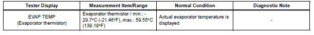
OK: The display is as specified in the normal condition column.
Result 


2 INSPECT EVAPORATOR TEMPERATURE SENSOR

(a) Disconnect the connector from the evaporator temperature sensor.
(b) Measure the resistance according to the value(s) in the table below.
Standard resistance 
NOTICE:
- Even slightly touching the sensor may change the resistance value. Be sure to hold the connector of the sensor.
- When measuring, the sensor temperature must be the same as the evaporator temperature.
HINT: As the temperature increases, the resistance decreases (see the graph).


3 CHECK HARNESS AND CONNECTOR (EVAPORATOR TEMPERATURE SENSOR - A/C AMPLIFIER)

(a) Disconnect the evaporator temperature sensor connector.

(b) Disconnect the A/C amplifier connector.
(c) Measure the resistance according to the value(s) in the table below.
Standard resistance 


REPLACE A/C AMPLIFIER
 Ambient temperature sensor circuit
DTC B1412/12 Ambient Temperature Sensor Circuit
DESCRIPTION
The ambient temperature sensor is installed in front of the condenser to
detect the ambient temperature
which is used to control the ai ...
 Rear evaporator temperature sensor circuit
DESCRIPTION
The rear evaporator temperature sensor is installed on the rear evaporator.
It detects the rear evaporator
temperature. The sensor sends a signal to the A/C amplifier. The resistance o ...
Other materials:
Display does not Dim when Light Control Switch is Turned ON
INSPECTION PROCEDURE
1 CHECK IMAGE QUALITY SETTING
Enter the display adjustment screen by pressing the
"DISPLAY" switch.
Turn the light control switch to the TAIL position.
Check if "DAY MODE" on the display adjustment is ON.
OK:
"DAY MODE" ...
Disassembly
1. REMOVE FRONT DISC BRAKE BUSH DUST BOOT
(a) Using soft jaws on the vise, hold the front disc brake
cylinder mounting LH in the vise through aluminum
plates.
(b) Using a screwdriver and hammer, remove the 2
front disc brake bush dust boots from the front disc
brake cylinder mounting LH. ...
Opening/closing the sliding door
Sliding door handle
Open/close
Vehicles with power sliding
doors: The sliding door will be
automatically and completely
opened and closed by the following.
Pulling the outside handle.
Sliding the inside handle forward
to close or backward to
open.
Power sliding door switches (v ...
