Toyota Sienna Service Manual: Fuel Pump Control Circuit
DESCRIPTION
The FUEL PUMP relay switches the fuel pump speed according to the engine conditions. The fuel pump operates when the ECM receives the starter-operating signal (STA) and crankshaft-rotating signal (NE).
The FUEL PUMP relay is turned ON while the engine is idling or operating at low load. This causes current to flow through the fuel pump resistor to the fuel pump. The fuel pump then operates at low speed.
The FUEL PUMP relay is turned OFF while the engine is cranking or operating at high load. The fuel pump then operates at normal speed.

WIRING DIAGRAM

INSPECTION PROCEDURE
1 CHECK FUEL PUMP
- Check if there is pressure in the fuel inlet hose.
HINT: If there is fuel pressure, the sound of fuel flowing will be heard
2 PERFORM ACTIVE TEST BY INTELLIGENT TESTER (OPERATE C/OPN RELAY)
- Connect the intelligent tester to the DLC3.
- Turn the ignition switch to the ON position and turn the intelligent tester or the OBD II scan tool main switch on.
- Enter the following menus: DIAGNOSIS / ENHANCED OBD II / ACTIVE TEST / FUEL PUMP / SPD.
- Check the relay operation while operating it using the intelligent tester.
Standard: Operating noise can be heard from the relay.
3 INSPECT RELAY (C/OPN RELAY)

- Remove the C/OPN relay from the engine room junction block.
- Measure the resistance according to the value(s) in the table below.
Standard resistance

- Reinstall the C/OPN relay.
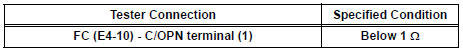
4 INSPECT ECM (FC VOLTAGE)

- Turn the ignition switch to the ON position.
- Measure the voltage according to the value(s) in the table below.
Standard voltage

5 CHECK HARNESS AND CONNECTOR (ECM - C/OPN RELAY)

- Disconnect the E4 ECM connector.
- Remove the C/OPN relay from the engine room junction block.
- Measure the resistance according to the value(s) in the table below.
Standard resistance: Check for open
Check for short

- Reconnect the ECM connector.
- Reinstall the C/OPN relay.
6 CHECK FUSE (IGN FUSE)

- Remove the IGN fuse from the driver side junction block.
- Measure the resistance according to the value(s) in the
table below.
Standard resistance: Below 1 Ω
- Reinstall the IGN fuse.
7 CHECK HARNESS AND CONNECTOR (C/OPN RELAY - IGNITION SWITCH)

- Reconnect the I15 ignition switch connector.
- Remove the C/OPN relay from the engine room junction block.
- Measure the resistance according to the value(s) in the table below.
Standard resistance: Check for open

Standard resistance: Check for short

- Reconnect the ignition switch connector.
- Reinstall the C/OPN relay.
8 CHECK ECM POWER SOURCE CIRCUIT
9 INSPECT RELAY (FUEL PUMP RELAY)

- Remove the fuel pump relay from the engine room junction block.
- Measure the resistance according to the value(s) in the table below.
Standard resistance
- Reinstall the fuel pump relay
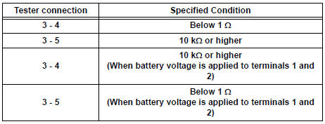
10 INSPECT FUEL PUMP

- Measure the resistance of the fuel pump.
- Measure the resistance according to the value(s) in the table below.
Standard resistance

- Check operation of the fuel pump.
- Apply battery voltage to both terminals. Check that the pump operates.
NOTICE:
- These tests must be done quickly (within 10 seconds) to prevent the coil from burning out.
- Keep the fuel pump as far away from the battery as possible
- Always turn ON and OFF the voltage on the battery side, not on the fuel pump side.
11 CHECK HARNESS AND CONNECTOR (FUEL PUMP - FUEL PUMP RELAY)

- Check the wire harness between the FUEL PUMP relay and fuel pump.
- Remove the FUEL PUMP relay from the engine room junction block.
- Disconnect the F20 fuel pump connector.
- Measure the resistance according to the value(s) in the table below.
Standard resistance

12 CHECK HARNESS AND CONNECTOR (FUEL PUMP - BODY GROUND)

- Check the wire harness between the fuel pump and body ground.
- Disconnect the F20 fuel pump connector.
- Measure the resistance between the terminal of the wire harness side connector and body ground.
Standard resistance

- Reinstall the FUEL PUMP relay.
- Reconnect the fuel pump connector.
13 CHECK HARNESS AND CONNECTOR (C/OPN RELAY - FUEL PUMP RELAY)

- Remove the C/OPN relay from the engine room junction block.
- Remove the FUEL PUMP relay from the engine room junction block.
- Measure the resistance according to the value(s) in the table below.
Standard resistance: Check for open

Check for short

- Reinstall the C/OPN relay.
- Reinstall the FUEL PUMP relay
14 INSPECT FUEL PUMP RESISTOR

- Disconnect the F24 fuel pump resistor connector.
- Measure the resistance according to the value(s) in the table below.
Standard resistance

- Reconnect the fuel pump resistor connector.
15 CHECK HARNESS AND CONNECTOR (FUEL PUMP RELAY - FUEL PUMP RESISTOR)

- Disconnect the F24 fuel pump resistor connector.
- Remove the FUEL PUMP relay from the engine room junction block.
- Measure the resistance according to the value(s) in the table below.
Standard resistance: Check for open

Check for short

- Reconnect the fuel pump resistor connector.
- Reinstall the FUEL PUMP relay.
16 CHECK HARNESS AND CONNECTOR (FUEL PUMP RESISTOR - FUEL PUMP)

- Disconnect the F24 fuel pump resistor connector.
- Disconnect the F20 fuel pump connector.
- Measure the resistance according to the value(s) in the table below.
Standard resistance: Check for open

Check for short

- Reconnect the fuel pump resistor connector.
- Reconnect the fuel pump connector.
PROCEED TO NEXT CIRCUIT INSPECTION SHOWN IN PROBLEM SYMPTOMS TABLE
 VC Output Circuit
DESCRIPTION
The ECM constantly uses 5 V from the battery voltages supplied to the +B (BATT)
terminal to operate the
microprocessor. The ECM also provides this power to the sensors through the VC
...
 Cranking Holding Function Circuit
DESCRIPTION
The system detects the ignition switch's starting signal (STSW) and then
supplies current to the starter
until the ECM judges that the engine has started successfully. The purpose is t ...
Other materials:
Adjustment
1. VEHICLE PREPARATION FOR HEADLIGHT AIMING
ADJUSTMENT
Prepare the vehicle:
Ensure there is no damage or deformation to the
body around the headlights.
Fill the fuel tank.
Make sure that the oil is filled to the specified
level.
Make sure that the c ...
Inspection
1. INSPECT FRONT DIFFERENTIAL
(a) Using a dial indicator, measure the backlash of one
pinion gear while holding the front differential side
gear toward the case.
Standard backlash:
0.05 - 0.20 mm (0.0020 - 0.0079 in.)
NOTICE:
Do not mount the surface of front differential
case which cont ...
Registration Complete Indication Error/ Registration Demand Transmission/
Multiple Frame Incomplete
DTC 01-E0 Registration Complete Indication Error
DTC 01-E3 Registration Demand Transmission
DTC 01-E4 Multiple Frame Incomplete
DESCRIPTION
DTC No.
DTC Detection Condition
Trouble Area
01-E0
"Registration complete" signal from the master device
c ...
