Toyota Sienna Service Manual: Headlight dimmer switch
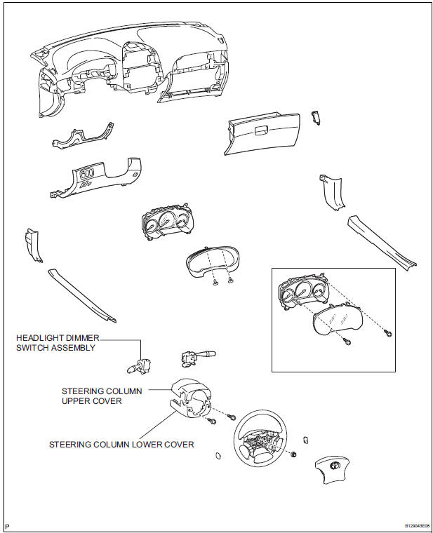
COMPONENTS
REMOVAL
1. REMOVE STEERING COLUMN LOWER COVER
2. REMOVE STEERING COLUMN UPPER COVER
3. REMOVE HEADLIGHT DIMMER SWITCH ASSEMBLY

- Disconnect the connector.
- Release the claw fitting and remove the headlight dimmer switch assembly.
INSPECTION
1. HEADLIGHT DIMMER SWITCH ASSEMBLY

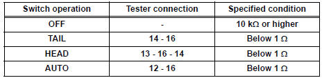
- Inspect light control switch resistance.
- Check that there is resistance between the terminals at each switch position as shown in the chart.
Resistance
- Inspect light control switch resistance.
- Check that there is resistance between the terminals at each switch position as shown in the chart.
Resistance

- Inspect light control switch resistance.
- Check that there is resistance between the terminals at each switch position as shown in the chart.
Resistance

- Inspect light control switch resistance.
- Check that there is resistance between the terminals at each switch position as shown in the chart.
Resistance

INSTALLATION
1. INSTALL HEADLIGHT DIMMER SWITCH ASSEMBLY
2. INSTALL STEERING COLUMN UPPER COVER
3. INSTALL STEERING COLUMN LOWER COVER
 Vanity light
ON-VEHICLE INSPECTION
1. LH VISOR ASSEMBLY
Inspect vanity light resistance.
check that the resistance exists between the
terminal 1 and the terminal 2 when the light is
oper ...
 Turn signal light switch
ON-VEHICLE INSPECTION
1. INSPECT TURN SIGNAL FLASHER CIRCUIT
Measure voltage between the terminals as shown in
the chart below.
Voltage
Connect the connector to turn the si ...
Other materials:
Open in Driver Side Squib 2nd Step Circuit
DTC B1181/18 Open in Driver Side Squib 2nd Step Circuit
DESCRIPTION
The driver side squib 2nd step circuit consists of the center airbag sensor
assembly, the spiral cable and
the steering pad.
The circuit instructs the SRS to deploy when deployment conditions are met.
DTC B1181/18 is reco ...
Installation
1. INSTALL 3 POINT TYPE NO. 2 REAR SEAT BELT ASSEMBLY
Check the degree of tilt when the belt begins to lock
the ELR.
Check that the belt does not lock within 15 of
tilt in all directions but that the belt locks with
over 45 of tilt, when gently moving the
retractor. ...
Reassembly
1. INSTALL NO. 1 SEAT CUSHION FRAME SUBASSEMBLY
LH
Install the seat cushion frame with the bolt.
Torque: Except 7-Passenger RH, M8 bolt
20.6 N*m (210 kgf*cm, 15 ft.*lbf)
M10 bolt
41 N*m (418 kgf*cm, 30 ft.*lbf)
2. INSTALL RECLINING CONTROL LINK SUBASSEMBLY
LH
Install ...
