Toyota Sienna Service Manual: Ignition Switch Circuit
DESCRIPTION
When the ignition switch is turned to the ON position, battery positive voltage is applied to terminal IG of the ECU. When battery positive voltage is applied to terminal IG of the ECU while the theft deterrent system is operating, the warning stops.
WIRING DIAGRAM

INSPECTION PROCEDURE
1 INSPECT FUSES (ECU-IG, AM1)
- Remove the ECU-IG and AM1 fuses from the instrument panel J/B.
- Measure the resistance.
Standard resistance: Below 1 Ω
2 INSPECT RELAY (IG1)

- Remove the IG1 relay from the instrument panel J/B.
- Check the operation of the IG1 relay.
Standard resistance

3 INSPECT IGNITION OR STARTER SWITCH ASSEMBLY
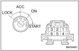
- Disconnect the I15 switch connector.
- Measure the resistance according to the value(s) in the table below.
Standard resistance

4 CHECK INSTRUMENT PANEL JUNCTION BLOCK ASSEMBLY (POWER SOURCE)
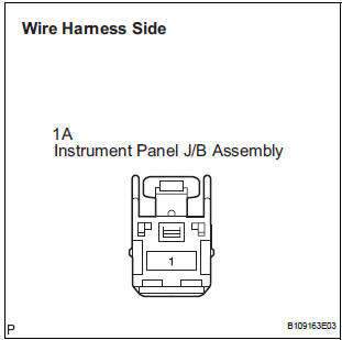
- Disconnect the 1A J/B connector.
- Turn the ignition switch ON.
- Measure the voltage according to the value(s) in the table below.
Standard voltage

REPLACE INSTRUMENT PANEL J/B ASSEMBLY
 Security Horn Circuit
DESCRIPTION
During the alarm sounding state, the relay in the ECU turns on and off in a
cycle of approximately 0.2
seconds, causing the security horn to sound.
WIRING DIAGRAM
INSPECTION PROC ...
 Security Indicator Light Circuit
DESCRIPTION
Even when the theft deterrent system is in the disarmed state, the security
indicator blinks due to a signal
output from the immobiliser system. The security indicator blinks continuou ...
Other materials:
Speed Signal Circuit
DESCRIPTION
The clearance warning ECU receives the vehicle speed signal from the
combination meter.
HINT:
A voltage of 12 V or 5 V is output from each ECU and then input to
the combination meter. The signal
is changed to a pulse signal at the transistor in the combination meter.
...
Power Window can be Operated After Ignition Switch is Turned OFF
Even if Operative Conditions are not Met
DESCRIPTION
The multiplex network body ECU controls power supplied to the power window
master switch and each
regulator switch continuously for 45 seconds after the ignition switch is turned
OFF unless the front doors
have been opened, so that the power window can be operated during this peri ...
Personal light assembly
ON-VEHICLE INSPECTION
1. ROOF CONSOLE BOX ASSEMBLY
Inspect map light assembly resistance.
Check the resistance between the terminals at
each switch position as shown in the chart.
Resistance
...