Toyota Sienna Service Manual: Illumination Circuit
DESCRIPTION
The Multiplex network body ECU controls illumination light as shown in the chart below.
- Room light assembly (Interior light, luggage component light) and courtesy light with DOOR position
- Map light assembly (Personal light)
- Transponder key amplifier (Ignition key cylinder light)
WIRING DIAGRAM


INSPECTION PROCEDURE
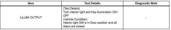
1 PERFORM ACTIVE TEST BY INTELLIGENT TESTER
- Connect the intelligent tester to DLC3.
- Turn the ignition switch ON and push the intelligent tester main switch ON.
- Select the item below in the ACTIVE TEST and then check that the relay operates
DATA LIST / AIR CONDITIONER
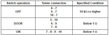
2 INSPECT LIGHT CONTROL RELAY

- Check that there is resistance between the terminals at each switch position as shown in the chart.
Resistance
3 INSPECT INTERIOR DOME LIGHT SWITCH ASSEMBLY
- Inspect interior dome light relay continuity.
Resistance

4 INSPECT INTERIOR LIGHT
- Inspect the each of interior light
5 INSPECT INSTRUMENT PANEL JUNCTION BLOCK ASSEMBLY
- Measure voltage between each of the terminals as shown in the chart below
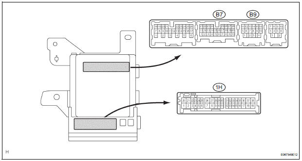
Voltage


PROCEED TO NEXT CIRCUIT INSPECTION SHOWN IN PROBLEM SYMPTOMS TABLE
 Door LOCK Position Circuit
DESCRIPTION
This circuit detects the state of the door lock detection sensor and send it
to the Multiplex network body
ECU.
WIRING DIAGRAM
INSPECTION PROCEDURE
1 READ VALUE OF INTELLIGENT T ...
 Parking Brake Switch Circuit
DESCRIPTION
The Multiplex network body ECU receives parking brake switch signal.
WIRING DIAGRAM
INSPECTION PROCEDURE
1 READ VALUE OF INTELLIGENT TESTER
Connect the intelligent tester to DL ...
Other materials:
Disassembly
HINT:
On the RH side, use the same procedures as on the LH side.
1. REMOVE FRONT DOOR LOWER FRAME BRACKET GARNISH LH
Using a screwdriver, disengage the clip and claw,
and remove the garnish.
HINT:
Tape the screwdriver tip before use.
2. REMOVE FRONT DOOR INSIDE HANDLE BEZEL PLUG LH
...
Reassembly
1. INSTALL NO. 2 SEAT LEG SUB-ASSEMBLY
Install the No. 2 seat leg sub-assembly with the 3
bolts and nut.
Torque: 19 N*m (194 kgf*cm, 14 ft.*lbf)
NOTICE:
Tighten the bolts and nuts in the order shown in
the illustration.
Install the 3 clamps.
2. INSTALL NO. 2 SEAT ...
Precaution
1. INSPECTION PROCEDURE FOR VEHICLE INVOLVED
IN ACCIDENT
Perform the zero point calibration and sensitivity
check if any of the following conditions occur.
The occupant classification ECU is replaced.
Accessories (seatback tray and seat cover, etc.)
are installed.
...
