Toyota Sienna Service Manual: Installation
1. INSTALL VANE PUMP ASSEMBLY
(a) Temporarily install the bolt to the vane pump assembly.
(b) Install the vane pump assembly.

(c) Temporarily install the bolt (B).
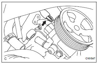
(d) Using SST, tighten the 2 bolts.
SST 09249-63010 Torque:Without SST 43 N*m (439 kgf*cm, 32 ft.*lbf) With SST 29 N*m (294 kgf*cm, 21 ft.*lbf)
NOTICE:
- Use a torque wrench with a fulcrum length of 300 mm (11.81 in.).
- This torque value is accurate when SST is parallel to the torque wrench.
2. CONNECT POWER STEERING FLUID PRESSURE SWITCH CONNECTOR
(a) Connect the connector to the power steering fluid pressure switch.
3. CONNECT PRESSURE FEED TUBE ASSEMBLY
(a) Install a new gasket to the pressure feed tube assembly.

(b) Temporarily connect the pressure feed tube assembly to the vane pump assembly with the union bolt.
(c) Fully tighten the union bolt
Torque: 50 N*m (510 kgf*cm, 37 ft.*lbf)
NOTICE: Make sure that the stopper of the pressure feed tube assembly contacts the vane pump assembly securely as shown in the illustration.
4. CONNECT NO. 1 FLUID RESERVOIR TO PUMP HOSE
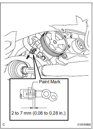
(a) Connect the No. 1 fluid reservoir to pump hose to the vane pump assembly with the clip.
NOTICE:
- Connect the No. 1 fluid reservoir to pump hose with the paint mark facing toward the rear of the vehicle.
- Push the No. 1 fluid reservoir to pump hose as far as it goes as shown in the illustration.
- Install the clip at the position specified in the illustration.
5. INSTALL FAN AND GENERATOR V BELT (See page EM-7)
6. ADD POWER STEERING FLUID
7. BLEED POWER STEERING SYSTEM (See page PS-6)
8. CHECK POWER STEERING FLUID LEVEL (See page PS-2)
9. INSPECT FOR POWER STEERING FLUID LEAK
10. INSTALL FRONT FENDER APRON SEAL RH (See page EM-62)
11. INSTALL FRONT WHEEL RH Torque: 103 N*m (1,050 kgf*cm, 76 ft.*lbf)
 Reassembly
NOTICE:
Before installation, coat the parts indicated by arrows
with power steering fluid (See page PS-7).
1. INSTALL VANE PUMP HOUSING OIL SEAL
(a) Coat a new vane pump housing oil seal lip with
...
 Rack and pinion power steering gear
COMPONENTS
...
Other materials:
Camshaft Position Sensor "A" Circuit
DTC P0340 Camshaft Position Sensor "A" Circuit (Bank 1
or Single Sensor)
DTC P0342 Camshaft Position Sensor "A" Circuit Low
Input (Bank 1 or Single Sensor)
DTC P0343 Camshaft Position Sensor "A" Circuit High
Input (Bank 1 or Single Sensor)
DTC P0345 Camshaft Posit ...
Short to B+ in Driver Side Squib Circuit
DTC B0103/12 Short to B+ in Driver Side Squib Circuit
DESCRIPTION
The driver side squib circuit consists of the center airbag sensor assembly,
the spiral cable and the
steering pad.
The circuit instructs the SRS to deploy when deployment conditions are met.
DTC B0103/12 is recorded when a ...
Removal
1. DISCHARGE REFRIGERANT FROM
REFRIGERATION SYSTEM
SST 07110-58060 (07117-58080, 07117-58090,
07117-78050, 07117-88060, 07117-88070,
07117-88080)
HINT:
See page AC-172.
2. REMOVE REAR DOOR SCUFF PLATE RH (See page
IR-7)
3. REMOVE BACK DOOR SCUFF PLATE (See page IR-
8)
4. REMOVE QUARTER TR ...
