Toyota Sienna Service Manual: Installation
1. INSTALL KNOCK CONTROL SENSOR

- Install the 2 knock control sensors with the 2 bolts
as shown in the illustration.
Torque: 20 N*m (204 kgf*cm, 15 ft.*lbf)
- Connect the 2 knock control sensor connectors.
2. INSTALL INTAKE MANIFOLD
3. INSTALL FUEL MAIN TUBE SUB-ASSEMBLY
4. INSTALL INTAKE AIR SURGE TANK
NOTICE: DO NOT apply oil to the bolts listed below.
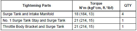
- Install a new gasket to the intake air surge tank [A].
- Using a 5 mm hexagon socket wrench, install the 4
bolts [B].
Torque: 18 N*m (184 kgf*cm, 13 ft.*lbf)
- Install the intake air surge tank with the 2 nuts and 2
bolts [C].
Torque: Nut 16 N*m (163 kgf*cm, 12 ft.*lbf)
Bolt 21 N*m (214 kgf*cm, 15 ft.*lbf)

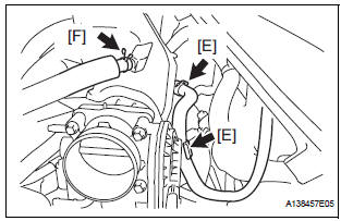
- Connect the connector [D].
- Connect the union to check valve hose [E].
- Connect the ventilation hose No. 2 [F].
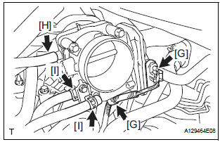
- Install the clamp and connect the throttle with motor body assembly connector [G].
- Connect the vapor feed hose [H].
- Connect the 2 water by-pass hoses to the throttle with motor body assembly [I].
5. INSTALL AIR CLEANER CASE SUB-ASSEMBLY
6. INSTALL AIR CLEANER CAP SUB-ASSEMBLY
7. ADD ENGINE COOLANT
8. INSPECT FOR ENGINE COOLANT LEAK
9. INSPECT FOR FUEL LEAK
10. INSTALL FRONT OUTER COWL TOP PANEL SUBASSEMBLY
11. INSTALL WINDSHIELD WIPER MOTOR ASSEMBLY
12. INSTALL V-BANK COVER SUB-ASSEMBLY
 Inspection
1. KNOCK CONTROL SENSOR
Using an ohmmeter, measure the resistance
between the terminals.
Resistance:
120 to 280 kΩ at 20C (68F)
If the resistance is not specified, replac ...
 EFI relay
Inspection
1. INSPECT EFI RELAY
(a) Using an ohmmeter, measure the resistance
according to the value(s) in the table below.
Standard resistance
If the result is not as specified, replace ...
Other materials:
Transfer
SST
RECOMMENDED TOOLS
EQUIPMENT
LUBRICANT
SSM
...
Removal
1. REMOVE FRONT WHEELS
2. REMOVE ENGINE UNDER COVER NO.1
3. DRAIN AUTOMATIC TRANSAXLE FLUID
(a) Remove the drain plug, gasket and drain ATF.
(b) Install a new gasket and the drain plug.
Torque: 49 N*m (500 kgf*cm, 36 ft.*lbf)
4. REMOVE FRONT DRIVE SHAFT ASSEMBLY LH
HINT:
(See page DS-6)
...
Installation
1. INSTALL WINDSHIELD GLASS NO.2 STOPPER
Coat the installation part of the stoppers with Primer
G.
NOTICE:
Allow the primer coating to dry for 3 minutes
or more.
Do not keep any of the opened Primer G for
later use.
Do not apply too much Primer .
...
