Toyota Sienna Service Manual: Installation
1. Install air fuel ratio sensor (for bank 2 sensor 1)

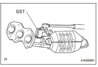
(a) Using SST, install the sensor to the exhaust manifold LH.
SST 09224-00010
Torque: 40 N*m (408 kgf*cm, 30 ft.*lbf) for use with SST 44 N*m (449 kgf*cm, 32 ft.*lbf) for use without SST
HINT:
- Use a torque wrench with a fulcrum length of 30 cm (11.81 in.).
- Make sure that SST and a wrench are connected in a straight line.
(b) Connect the sensor connector
2. INSTALL AIR FUEL RATIO SENSOR (for Bank 1 Sensor 1)
(a) Using SST, install the sensor to the exhaust manifold RH.
SST 09224-00010
Torque: 40 N*m (408 kgf*cm, 30 ft.*lbf) for use with SST
44 N*m (449 kgf*cm, 32 ft.*lbf) for use without SST
HINT:
- Use a torque wrench with a fulcrum length of 30 cm (11.81 in.).
- Make sure that SST and wrench are connected in a straight line.
3. INSTALL EXHAUST MANIFOLD RH

(a) Install the exhaust manifold RH with a new gasket and 6 nuts.
Torque: 21 N*m (214 kgf*cm, 15 ft.*lbf)

(b) Install the exhaust manifold stay with the nut and bolt.
Torque: 35 N*m (357 kgf*cm, 26 ft.*lbf) (c) Connect the air fuel ratio sensor (for Bank 1 Sensor 2) connector.
4. INSTALL FRONT EXHAUST PIPE ASSEMBLY

(a) Check compression springs.
(1) Check the compression springs using vernier calipers.
Specified length: 38.86 mm (1.5299 in.)
HINT:
If the result is not as specified, replace the compression spring.

(b) Install the gasket.
(1) Install a new gasket by hand onto the front exhaust pipe assembly.
(2) Using a plastic hammer and wooden block, tap in the new gasket until its surface is flush with the front exhaust pipe.
NOTICE:
|
(c) Install 2 new gaskets to the front exhaust pipe assembly.
(d) Install the front exhaust pipe assembly with the 4 nuts.
Torque: 62 N*m (632 kgf*cm, 46 ft.*lbf)


(e) Install the center exhaust pipe assembly with the 2 compression springs and 2 bolts.
Torque: 43 N*m (438 kgf*cm, 32 ft.*lbf) (f) Install the No. 1 exhaust pipe support bracket with the 2 new nuts.
Torque: 21 N*m (214 kgf*cm, 15 ft.*lbf)

(g) Connect the heated oxygen sensor (for Bank 1 sensor 2) connector
5. CONNECT CABLE TO NEGATIVE BATTERY TERMINAL
6. INSPECT FOR EXHAUST GAS LEAK
 Inspection
1. INSPECT AIR FUEL RATIO SENSOR
(a) Measure the resistance of the sensor.
Standard resistance
If the resistance is not as specified, replace the
sensor. ...
 Air fuel ratio sensor (for 4wd)
Components
...
Other materials:
Unlock warning switch
INSPECTION
1. INSPECT UNLOCK WARNING SWITCH ASSEMBLY
Remove the unlock warning switch assembly .
Measure the resistance according to the value(s) in
the table below.
Standard resistance
...
Installation
1. INSTALL HEADLIGHT ASSEMBLY
Connect the connectors.
Install the headlight assembly with the bolt and 3
screws.
2. INSTALL FRONT BUMPER ASSEMBLY
3. CONNECT CABLE TO NEGATIVE BATTERY
TERMINAL
4. VEHICLE PREPARATION FOR HEADLIGHT AIMING
5. PREPARATION FOR HEADLIGHT AIMI ...
Installation
1. INSTALL PARKING BRAKE CABLE ASSEMBLY NO.3
(a) Install the parking brake cable LH guide to the
parking brake cable assembly No. 3.
(b) Connect the parking brake cable No. 3 to the
parking brake cable equalizer.
(c) Install the parking brake cable No. 3 with the 3 bolts
and button.
T ...
