Toyota Sienna Service Manual: Installation
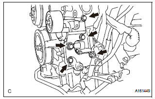
1. INSTALL WATER PUMP ASSEMBLY

(a) Install a new water pump gasket and the water pump assembly with the 16 bolts.
Torque: Bolt A 21 N*m (214 kgf*cm, 15 ft.*lbf) Bolts B and C 9.1 N*m (93 kgf*cm, 81 in.*lbf)
NOTICE:
|
2. INSTALL WATER INLET HOUSING

(a) Install a new water inlet housing No. 1 gasket and water outlet pipe O-ring.
(b) Install the water inlet housing with the 2 bolts and nut.

Torque: 10 N*m (102 kgf*cm, 7 ft.*lbf)
| NOTICE: Be careful not to allow the O-ring to get caught between the parts. |
(c) Connect the water hose.
3. INSTALL WATER PUMP PULLEY

(a) Temporarily install the water pump pulley with the 4 bolts.
(b) Using SST, hold the water pump pulley.
SST 09960-10010 (09962-01000, 09963-00700) (c) Tighten the 4 bolts.
Torque: 21 N*m (214 kgf*cm, 15 ft.*lbf)
4. INSTALL V-RIBBED BELT TENSIONER ASSEMBLY
(a) Install the V-ribbed belt tensioner assembly with the 5 bolts.
Torque: 43 N*m (438 kgf*cm, 32 ft.*lbf)
5. INSTALL NO. 2 IDLER PULLEY SUB-ASSEMBLY

(a) Install the 2 idler pulley cover plates and idler pulley sub-assemblies with the 2 bolts.
Torque: 43 N*m (438 kgf*cm, 32 ft.*lbf)
6. INSTALL NO. 1 ENGINE FRONT MOUNTING BRACKET LH (See page EM-45) 7. INSTALL GENERATOR ASSEMBLY (See page CH-26) 8. INSTALL COMPRESSOR AND MAGNETIC CLUTCH (See page AC-231) 9. INSTALL ENGINE HANGERS (See page EM-50) 10. REMOVE ENGINE STAND 11. INSTALL ENGINE ASSEMBLY WITH TRANSAXLE HINT: See page EM-44 12. ADD ENGINE COOLANT (See page CO-7) 13. INSPECT FOR COOLANT LEAK (See page CO-1)
 Inspection
1. Inspect water pump assembly
(a) Visually check the drain hole and air hole for coolant
leakage.
(b) Turn the pulley, and check that the water pump
bearing moves smoothly and noiselessly.
...
 Thermostat
Components
...
Other materials:
Knock sensor
COMPONENTS
REMOVAL
1. DISCHARGE FUEL SYSTEM PRESSURE
(See page FU-13)
2. REMOVE V-BANK COVER SUB-ASSEMBLY (See
page EM-28)
3. DRAIN ENGINE COOLANT (See page CO-6)
4. REMOVE WINDSHIELD WIPER MOTOR ASSEMBLY
HINT:
(See page WW-4)
5. REMOVE FRONT OUTER COWL TOP PANEL SUBASSEMBLY
( ...
Passenger Side Outer Mirror ECU
DTC B1208 Passenger Side Outer Mirror ECU
DESCRIPTION
This DTC is detected when communication between the outer mirror control ECU
RH and multiplex
network gateway ECU stops for more than 10 seconds.
DTC No.
DTC Detecting Condition
Trouble Area
B1208
Pa ...
Open in Stop Light Switch Circuit
DTC C1249/49 Open in Stop Light Switch Circuit
DESCRIPTION
This skid control ECU inputs the stop light switch signal and detects the
status of brake operation.
The skid control ECU has an open detection circuit. If an open in the stop light
switch input line or GND
side stop light circuit ...
