Toyota Sienna Service Manual: Low Battery Positive Voltage
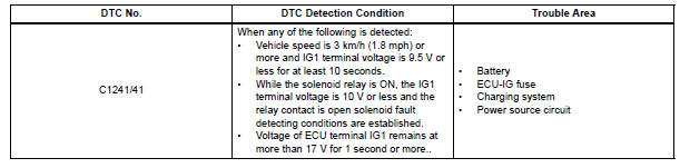
DTC C1241/41 Low Battery Positive Voltage
DESCRIPTION
If there is a problem with the brake actuator assembly (skid control ECU) power supply circuit, the skid control ECU outputs the DTC and prohibits the ABS operation with the fail safe function.
If the voltage supplied to the IG1 terminal is not within the DTC detection threshold due to malfunctions in such as the battery and alternator circuit, this DTC is stored.
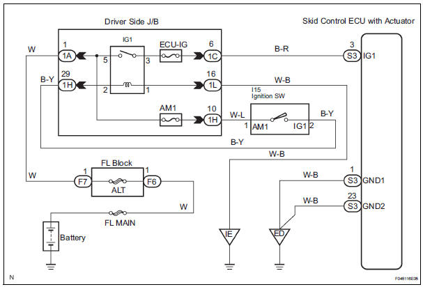
WIRING DIAGRAM
INSPECTION PROCEDURE
HINT: After steps 1 and 2 are completed, start the inspection from step 3 when using the intelligent tester, and from step 4 when not using the intelligent tester.
1 INSPECT BATTERY
(a) Check the battery voltage.
Standard voltage: 11 to 14 V


2 INSPECT FUSE (ECU-IG FUSE)

(a) Remove the ECU-IG fuse from the driver side J/B.
(b) Measure the resistance according to the value(s) in the table below.
Standard resistance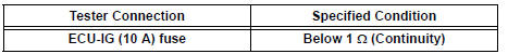


3 READ VALUE OF INTELLIGENT TESTER (IG1 POWER SUPPLY)
(a) Install the ECU-IG fuse.
(b) Connect the intelligent tester to the DLC3.
(c) Turn the ignition switch to the ON position and turn the intelligent tester main switch on.
(d) Start the engine.
(e) Select the DATA LIST mode on the intelligent tester.
ABS: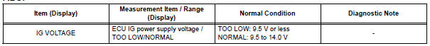
(f) Measure the voltage output from the ECU displayed on the intelligent tester.
OK: "Normal" is displayed.


4 INSPECT SKID CONTROL ECU (IG1 TERMINAL VOLTAGE)
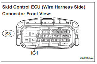
(a) Disconnect the skid control ECU connector.
(b) Turn the ignition switch to ON position.
(c) Measure the voltage according to the value(s) in the table below.
Standard voltage 


5 INSPECT SKID CONTROL ECU (GND TERMINAL CONTINUITY)
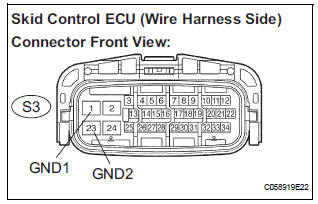
(a) Turn the ignition switch off.
(b) Measure the resistance according to the value(s) in the table below.
Standard resistance

6 RECONFIRM DTC
(a) Clear the DTCs (See page BC-10).
(b) Check that the same DTC is recorded (See page BC- 10).
HINT: Reinstall the sensors, connectors, etc. and restore the vehicle to its prior condition before rechecking for DTCs.
Result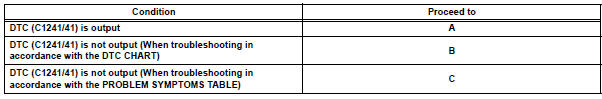


REPLACE BRAKE ACTUATOR ASSEMBLY
 Open in ABS Solenoid Relay Circuit
DESCRIPTION
This relay supplies power to each ABS solenoid.
Immediately after the ignition switch is turned to the ON position, the relay
turns on if the solenoid is
determined to be normal ...
 Open in Stop Light Switch Circuit
DTC C1249/49 Open in Stop Light Switch Circuit
DESCRIPTION
This skid control ECU inputs the stop light switch signal and detects the
status of brake operation.
The skid control ECU has an open ...
Other materials:
Receiver Error
DTC C2176/76 Receiver Error
DESCRIPTION
The signals are transmitted to the tire pressure warning antenna and receiver
on the body as radio waves
and then sent to the tire pressure warning ECU.
WIRING DIAGRAM
INSPECTION PROCEDURE
NOTICE:
When replacing the tire pressure warning EC ...
DTC check / clear
1. CHECK DTC (USING INTELLIGENT TESTER)
Checking DTCs.
Connect the intelligent tester to the DLC3.
Turn the ignition switch ON.
Read DTCs by following the prompts on the
tester screen.
HINT:
Refer to the intelligent tester operator's manual
for further deta ...
Removal
1. DISCHARGE REFRIGERANT FROM
REFRIGERATION SYSTEM
SST 07110-58060 (07117-58080, 07117-58090,
07117-78050, 07117-88060, 07117-88070,
07117-88080)
HINT:
See page AC-172.
2. REMOVE REAR DOOR SCUFF PLATE RH (See page
IR-7)
3. REMOVE BACK DOOR SCUFF PLATE (See page IR-
8)
4. REMOVE QUARTER TR ...
