Toyota Sienna Service Manual: Mass air flow meter
COMPONENTS

ON-VEHICLE INSPECTION
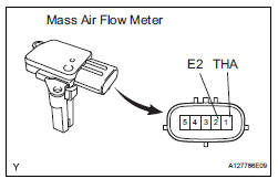
1. INSPECT MASS AIR FLOW METER

NOTICE:
|
(a) Read the values using the intelligent tester (MAF).
NOTICE:
|
(1) Turn the ignition switch to the ON position (do not start the engine).
(2) Turn the tester on.
(3) Select the following menu items: DIAGNOSIS / ENHANCED OBD II / DATA LIST / PRIMARY / PRIMARY / MAF.
(4) Wait 30 seconds, and read the values on the intelligent tester.
Standard condition: Less than 0.70 g/s
- If the result is not as specified, replace the MAF meter.
- If the result is within the specified range, inspect the cause of the extremely rich or lean air fuel ratio.
REMOVAL
1. REMOVE MASS AIR FLOW METER

(a) Disconnect the mass air flow meter connector.
(b) Remove the 2 screws and mass air flow meter.
INSPECTION
1. INSPECT MASS AIR FLOW METER
(a) Visually check for any foreign matter on the platinum hot wire (heater) of the mass air flow meter.
OK: There is no foreign matter.
If the result is not as specified, replace the mass air flow meter.
(b) Measure the resistance according to the value(s) in the table below.
Standard resistance

INSTALLATION
1. REMOVE MASS AIR FLOW METER

(a) Install the mass air flow meter with the 2 screws.
(b) Connect the mass air flow meter connector.
 Accelerator pedal rod
COMPONENTS
ON-VEHICLE INSPECTION
1. CHECK ACCELERATOR PEDAL ROD
(a) Check the voltage.
(1) Connect the intelligent tester to the DLC3.
(2) Turn the ignition switch to the ON position.
...
 Vvt sensor
COMPONENTS
ON-VEHICLE INSPECTION
1. CHECK VVT SENSOR OUTPUT VOLTAGE
(a) Turn the ignition switch to the ON position.
(b) Check the voltage between the specified terminal
and body grou ...
Other materials:
Display
When the sensors detect an obstacle, the following displays inform
the driver of the position and distance to the obstacle.
Multi-information display
Front corner sensor operation
Rear corner sensor operation
Rear center sensor operation
Audio system screen
Intuitive parking ...
Camshaft Position "B" Actuator Circuit / Open
DTC P0013 Camshaft Position "B" Actuator Circuit / Open
(Bank 1)
DTC P0023 Camshaft Position "B" Actuator Circuit / Open
(Bank 2)
DESCRIPTION
The Variable Valve Timing (VVT) system includes the ECM, OCV and VVT
controller. The ECM sends a
target duty-cycle control signal ...
Diagnostic trouble code chart
COMMUNICATION DIAGNOSIS:
SW:
SW WITH NAME:
SW CONVERTING:
COMMAND SW:
FRONT MONITOR:
DVD PLAYER:
TELEPHONE:
NAVI:
IN-DASH CD CHANGER:
GPS:
CAMERA UNIT:
...
