Toyota Sienna Service Manual: Open in Driver Side Squib Circuit
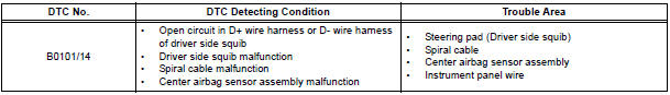
DTC B0101/14 Open in Driver Side Squib Circuit
DESCRIPTION
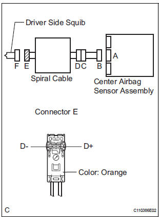
The driver side squib circuit consists of the center airbag sensor assembly, the spiral cable and the steering pad.
The circuit instructs the SRS to deploy when deployment conditions are met.
DTC B0101/14 is recorded when an open circuit is detected in the driver side squib circuit.
WIRING DIAGRAM
INSPECTION PROCEDURE
HINT:
- Perform the simulation method by selecting the "check mode" (signal check) with the intelligent tester.
- After selecting the "check mode" (signal check), perform the simulation method by wiggling each connector of the airbag system or driving the vehicle on a city or rough road
1 CHECK STEERING PAD (DRIVER SIDE SQUIB)

- Turn the ignition switch to the LOCK position.
- Disconnect the negative (-) terminal cable from the battery, and wait for at least 90 seconds.
- Disconnect the connectors from the steering pad.
- Connect the white wire side of SST (resistance 2.1 Ω) to the spiral cable.
CAUTION: Never connect a tester to the steering pad (driver side squib) for measurement, as this may lead to a serious injury due to airbag deployment.
NOTICE: Do not forcibly insert the SST into the terminals of the connector when connecting.
Insert the SST straight into the terminals of the connector.
SST 09843-18060
- Connect the negative (-) terminal cable to the battery, and wait for at least 2 seconds.
- Turn the ignition switch to the ON position, and wait for at least 60 seconds.
- Clear the DTCs stored in memory.
- Turn the ignition switch to the LOCK position.
- Turn the ignition switch to the ON position, and wait for at least 60 seconds.
- Check the DTCs.
OK: DTC B0101/14 is not output.
HINT: Codes other than DTC B0101/14 may be output at this time, but they are not related to this check.
REPLACE STEERING PAD
2 CHECK DRIVER SIDE SQUIB CIRCUIT
- Turn the ignition switch to the LOCK position.
- Disconnect the negative (-) terminal cable from the battery, and wait for at least 90 seconds.
- Disconnect the SST (resistance 2.1 Ω) from the spiral cable.
- Disconnect the connector from the center airbag sensor assembly.
- Measure the resistance according to the value(s) in the table below.
Standard resistance
3 CHECK CENTER AIRBAG SENSOR ASSEMBLY

- Connect the connectors to the steering pad and the center airbag sensor assembly.
- Connect the negative (-) terminal cable to the battery, and wait for at least 2 seconds.
- Turn the ignition switch to the ON position, and wait for at least 60 seconds.
- Clear the DTCs stored in memory.
- Turn the ignition switch to the LOCK position.
- Turn the ignition switch to the ON position, and wait for at least 60 seconds.
- Check the DTCs.
OK: DTC B0101/14 is not output.
HINT: Codes other than code B0101/14 may be output at this time, but they are not related to this check.

USE SIMULATION METHOD TO CHECK
4 CHECK INSTRUMENT PANEL WIRE
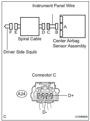
- Disconnect the instrument panel wire connector from the spiral cable.
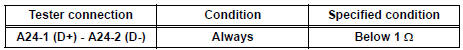
- Measure the resistance according to the value(s) in the table below.
Standard resistance
5 CHECK SPIRAL CABLE

- Measure the resistance according to the value(s) in the table below.
Standard resistance

USE SIMULATION METHOD TO CHECK
 Short in Driver Side Squib Circuit
DTC B0100/13 Short in Driver Side Squib Circuit
DESCRIPTION
The driver side squib circuit consists of the center airbag sensor assembly,
the spiral cable and the
steering pad. The circuit instruc ...
 Short to GND in Driver Side Squib Circuit
DTC B0102/11 Short to GND in Driver Side Squib Circuit
DESCRIPTION
The driver side squib circuit consists of the center airbag sensor assembly,
the spiral cable and the
steering pad.
The circu ...
Other materials:
Deactivating or stopping the alarm
Do one of the following to deactivate or stop the alarm:
Unlock the doors using the entry function (vehicles with a smart
key
system) or wireless remote control.
Vehicles without a smart key system: Turn the engine switch to the
“ACC” or “ON” position, or start the engine.
Veh ...
Folding and extending the mirrors
Manual type
Push the mirror back in the direction
of the vehicle’s rear.
Power type
Press the switch.
Folding
Extending
...
Problem symptoms table
HINT:
Use the table below to help determine the cause of the
problem symptom. The likely causes of the problem are
indicated in descending order. Check each suspected area
in order. Repair or replace faulty parts or perform
adjustments as necessary.
Inspect the fuse and rel ...
