Toyota Sienna Service Manual: Perform zero point calibration of yaw rate and deceleration sensor (when using sst check wire)
NOTICE:
- While obtaining the zero point, do not vibrate the vehicle by tilting, moving or shaking it and keep it in a stationary condition. (Do not turn the ignition switch to the ON position.)
- Be sure to do this on a level surface (with an inclination of less than 1 %).

(a) Procedures for test mode.
(1) Check that the steering wheel is in the straightahead position and move the shift lever to the P position and apply the parking brake.
(2) Connect the intelligent tester to the DLC3.
(3) Turn the ignition switch to the ON position.

(4) Set the intelligent tester to test mode (select "TEST MODE").
HINT: Refer to the intelligent tester operator's manual for further details.
(b) Obtain the zero point of the yaw rate and deceleration sensor.
(1) Keep the vehicle in the stationary condition on a level surface for 2 seconds or more.

(2) Check that the ABS warning light and VSC warning light blink.
HINT:
- If the ABS warning light and VSC warning light do not blink perform zero point calibration again.
- The zero point calibration is performed only once after the system enters the test mode.
- Calibration cannot be performed again until the stored data is cleared once.
(c) Turn the ignition switch off and disconnect the intelligent tester.
PERFORM ZERO POINT CALIBRATION OF YAW RATE AND DECELERATION SENSOR (WHEN USING SST CHECK WIRE):
NOTICE:
- While obtaining the zero point, do not vibrate the vehicle by tilting, moving or shaking it and keep it in a stationary condition. (Do not turn the ignition switch to the ON position.)
- Be sure to do this on a level surface (with an inclination of less than 1 %).
(a) Clear the zero point calibration.
(1) Turn the ignition switch to the ON position.
(2) Using SST, connect and disconnect terminals TS and CG of the DLC3 4 times or more within 8 seconds.
SST 09843-18040
(b) Procedures for test mode.
(1) Turn the ignition switch off.
(2) Using SST, connect terminals TS and CG of the DLC3.
SST 09843-18040

(3) Check that the steering wheel is in the straightahead position and move the shift lever to the P position.
(c) Obtain the zero point of the yaw rate and deceleration sensor.
(1) Turn the ignition switch to the ON position.
(2) Keep the vehicle in a stationary condition on a level surface for 2 seconds or more.
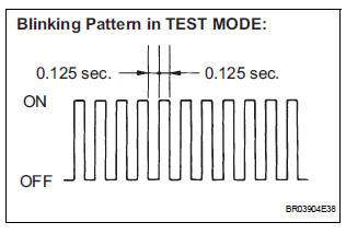
(3) Check that the ABS warning light and VSC light blink (test mode).
HINT:
- If the ABS warning light and VSC warning light do not blink perform zero point calibration again.
- The zero point calibration is performed only once after the system enters the test mode.
- Calibration cannot be performed again until the stored data is cleared once.
(d) Turn the ignition switch off and disconnect the SST from the DLC3.
 Perform zero point calibration of yaw rate and deceleration sensor (when
using intelligent tester)
Perform zero point calibration of yaw rate and deceleration sensor (when
using intelligent tester)
(a) Connect the intelligent tester to the DLC3.
(b) Turn the ignition switch to the ON position.
(c) Operate the intelligent tester to erase the codes
(select "RESET MEMORY").
...

Other materials:
Removal
1. REMOVE INSTRUMENT PANEL SUB-ASSEMBLY WITH PASSENGER AIRBAG ASSEMBLY
HINT:
Refer to the instructions for removal of the instrument
panel sub-assembly w/ passenger airbag assembly (See
page IP-5).
2. REMOVE HEATER TO FOOT DUCT NO.1
(a) Remove the clip and the heater to foot duct No. 1.
3 ...
Driving Position Memory Switch Circuit (w/ Memory)
DESCRIPTION
The seat memory switch sends signals to the outer mirror control ECU LH via
the multiplex
communication system to memorize a given seat position. This memory system does
not use a position
sensor. The seat position is detected by counting pulses that are output when
the motor tu ...
TC and CG Terminal Circuit
DESCRIPTION
Connecting terminals TC and CG of the DLC3 causes the system to enter the
self-diagnostic mode. If a
malfunction is present, DTCs will be output.
HINT:
When a particular warning light remains blinking, a ground short in the wiring
of terminal TC of the DLC3
or an internal ground ...
