Toyota Sienna Service Manual: Power Back Door Warning Buzzer does not Sound
DESCRIPTION
- The power back door system uses a warning buzzer built into the back door, which has 3 ways of sounding that are used differently according to the situations:
- When all the following conditions are met, the warning buzzer sounds at
a cycle of 0.3 seconds:
* The ignition switch is turned ON.
* The shift lever is moved into any position except P position.
* The back door is open or the power back door is activated to open.
The warning buzzer continues to sound until the back door is fully closed or the shift lever is moved into the P position.
- While the power back door is operating, the warning buzzer sounds at a cycle of 0.7 seconds. The warning buzzer turns off when the power back door stops. This way of sounding is set to OFF at factory (default setting) and can be customized when required.
- hen the power back door is activated to open, the warning buzzer that notifies the start of opening of the power back door sounds at 2 cycles of 0.5 seconds. At the start of opening of the power back door, a wireless buzzer (built into the engine room) also sounds.
- The power back door ECU directly sends a signal to the warning buzzer.
HINT:
- Only item 2 can be customized .
- If all items occur at the same time, item 1 is prior to the others.
WIRING DIAGRAM
INSPECTION PROCEDURE
1 PERFORM ACTIVE TEST BY INTELLIGENT TESTER
- Select the ACTIVE TEST and then check that the power back door warning buzzer operates.
HINT: During the ACTIVE TEST, the intelligent tester sends a signal to the power back door ECU to drive the warning buzzer. If the warning buzzer operates, the warning buzzer itself and the wire harness between the warning buzzer and power back ECU are considered to be functioning normally.
OK (Power slide door ECU):

2 CHECK WIRE HARNESS (POWER BACK DOOR WARNING BUZZER WIRE HARNESS SIDE)

- Remove the buzzer connector.
- Inspect the buzzer connector side voltage.

NOTICE: Use an oscilloscope to check the output voltages of the buzzer.
Voltage

3 INSPECT POWER BACK DOOR WARNING BUZZER

- Check the resistance of the buzzer.
Resistance

NOTICE:
- The circuit that causes the buzzer to sounds is built into the back door ECU, not around the buzzer.
- Directly applying battery voltage to the buzzer does not cause the buzzer to sound.
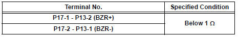
4 CHECK WIRE HARNESS (POWER BACK DOOR WARNING BUZZER - POWER BACK DOOR ECU)

- Disconnect the P17 buzzer and the P13 ECU connectors.
- Check the resistance between the wire harness side connectors.
Resistance (Check for open circuit)
REPLACE POWER BACK DOOR ECU
 Jam Protection Function Activates During Power Back Door Operation
DESCRIPTION
It may be caused by ill-fitting back door, faulty touch sensor or
faulty pulse sensor.
The power back door ECU activates the back motor to open / close
the power back door, thu ...
 Hood
Hood
COMPONENTS
Adjustment
HINT:
Since a centering bolt is used as a hood hinge mounting bolt
and hood lock mounting bolt, the hood and hood lock can not
be adjusted with them on. Substitute a bolt ...
Other materials:
Power window regulator
motor
INSPECTION
1. INSPECT POWER WINDOW REGULATOR MOTOR
(FRONT RH)
Remove the power window regulator motor.
Apply battery voltage to the motor connector
according to the table below.
NOTICE:
Do not apply battery to any terminals except
terminals 1 and 2.
Standard
2. INS ...
Installation
1. INSTALL HEADLIGHT ASSEMBLY
Connect the connectors.
Install the headlight assembly with the bolt and 3
screws.
2. INSTALL FRONT BUMPER ASSEMBLY
3. CONNECT CABLE TO NEGATIVE BATTERY
TERMINAL
4. VEHICLE PREPARATION FOR HEADLIGHT AIMING
5. PREPARATION FOR HEADLIGHT AIMI ...
Installation
1. INSTALL SPARK PLUG
(a) Install the 6 spark plugs.
Torque: 18 N*m (183 kgf*cm, 13 ft.*lbf)
2. INSTALL IGNITION COIL ASSEMBLY
(a) Install the 6 ignition coils with the 6 bolts.
Torque: 10 N*m (102 kgf*cm, 7 ft.*lbf)
(b) Connect the 6 ignition coil connectors.
3. INSTALL NO. 1 SUR ...
