Toyota Sienna Service Manual: Power Seat ECU Communication Stop
DTC B1272 Power Seat ECU Communication Stop
DESCRIPTION
This DTC is detected when communication between the seat position control ECU and the multiplex network gateway ECU stops for more than 10 seconds.
|
DTC No. |
DTC Detection Condition |
Trouble Area |
|
B1272 |
Power seat ECU communication stops |
|
WIRING DIAGRAM

INSPECTION PROCEDURE
1 CHECK HARNESS AND CONNECTOR (SEAT POSITION CONTROL ECU - BATTERY)
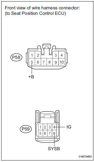
- Disconnect the P58 and P59 ECU connectors.
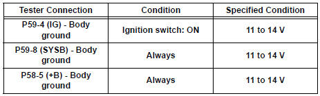
- Measure the voltage according to the value(s) in the table below.
Standard voltage
2 CHECK HARNESS AND CONNECTOR (SEAT POSITION CONTROL ECU - GROUND)

- Measure the resistance according to the value(s) in the table below.
Standard resistance

3 CHECK COMMUNICATION LINE
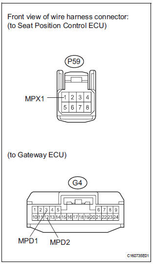
- Disconnect the G4 ECU connector.
- Measure the resistance according to the value(s) in the table below.
Standard resistance

Result

REPLACE SEAT POSITION CONTROL ECU
 Combination Meter ECU Communication Stop
DTC B1271 Combination Meter ECU Communication Stop
DESCRIPTION
DTC B1271 is output when communication between the combination meter and the
multiplex network
gateway ECU stops for more than 10 se ...
 Airbag ECU Communication Stop
DTC B1281 Airbag ECU Communication Stop
DESCRIPTION
DTC B1281 is output when communication between the airbag ECU and the
multiplex network gateway
ECU stops for more than 10 seconds.
...
Other materials:
Check and replace ecu
NOTICE: • The connector should not be disconnected from
the ECU. Perform the inspection from the
backside of the connector on the wire harness
side.
• When no measuring condition is specified,
perform the inspection with the engine stopped
and the ignition switch on.
• Che ...
Headlight Relay Circuit
DESCRIPTION
The Multiplex network body ECU controls HEAD relay when signal is received
from headlight dimmer
switch assembly.
WIRING DIAGRAM
INSPECTION PROCEDURE
1 PERFORM ACTIVE TEST BY INTELLIGENT TESTER
Connect the intelligent tester to DLC3.
Turn the ignition switch ON and ...
Starter Relay Circuit High
DTC P0617 Starter Relay Circuit High
MONITOR DESCRIPTION
While the engine is being cranked, the positive battery voltage is applied to
terminal STA of the ECM.
If the ECM detects the Starter Control (STA) signal while the vehicle is being
driven, it determines that
there is a malfunction i ...
