Toyota Sienna Service Manual: Pressure Control Solenoid "B" Performance (Shift Solenoid Valve SL2)
SYSTEM DESCRIPTION
The ECM uses signals from the vehicle speed sensor to detect the actual gear position (1st, 2nd, 3rd, 4th or 5th gear).
Then the ECM compares the actual gear with the shift schedule in the ECM memory
to detect mechanical
problems of the shift solenoid valves, valve body or automatic transaxle
(clutch, brake or gear etc.).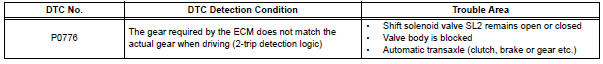
MONITOR DESCRIPTION
The ECM commands gear shifts by turning the shift solenoid valves "ON/OFF". According to the input shaft revolution, intermediate (counter) shaft revolution and output shaft revolution, the ECM detects the actual gear position (1st, 2nd, 3rd, 4th or 5th gear position). When the gear position commanded by the ECM and the actual gear position are not the same, the ECM illuminates the MIL and stores the DTC.
MONITOR STRATEGY

TYPICAL ENABLING CONDITIONS
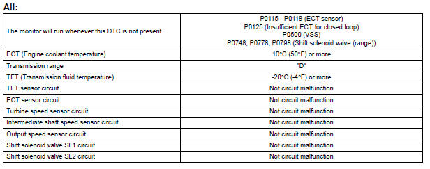
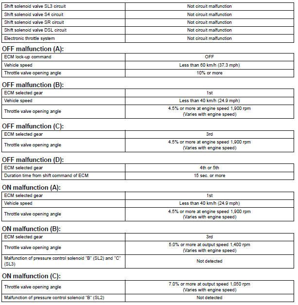
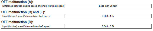
TYPICAL MALFUNCTION THRESHOLDS
Either of the following conditions is met: OFF malfunction (A), (B), (C) and (D), or ON malfunction (A), (B) and (C)

INSPECTION PROCEDURE
HINT: Using the intelligent tester to perform ACTIVE TEST allows relays, VSVs, actuators and other items to be operated without removing any parts. This non-intrusive functional inspection can be very useful because intermittent operation may be discovered before parts or wiring is disturbed. Performing ACTIVE TEST early in troubleshooting is one way to save diagnostic time. DATA LIST information can be displayed while performing ACTIVE TEST.
1. PERFORM ACTIVE TEST
(a) Warm up the engine.
(b) Turn the ignition switch off.
(c) Connect the intelligent tester together with the CAN VIM (controller area network vehicle interface module) to the DLC3.
(d) Turn the ignition switch to the ON position.
(e) Turn on the tester.
(f) Select the item "DIAGNOSIS / ENHANCED OBD II / ACTIVE TEST / SHIFT".
(g) According to the display on the tester, perform the "ACTIVE TEST".
HINT: While driving, the shift position can be forcibly changed with the intelligent tester.
Comparing the shift position commanded by the ACTIVE TEST with the actual shift
position enables you
to confirm the problem (See page AX-30).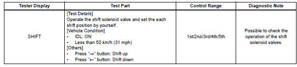
HINT:
- This test can be conducted when the vehicle speed is 50 km/h (31 mph) or less.
- The shift position commanded by the ECM is shown in the DATA LIST/SHIFT display on the intelligent tester.
1 CHECK OTHER DTCS OUTPUT (IN ADDITION TO DTC P0776)
(a) Connect the intelligent tester together with the CAN VIM (controller area network vehicle interface module) to the DLC3.
(b) Turn the ignition switch to the ON position and turn the OBD II scan tool or the intelligent tester main switch ON.
(c) When you use intelligent tester:
Select the item "DIAGNOSIS / ENHANCED OBD II / DTC INFO / CURRENT CODES".
(d) Read the DTCs using the OBD II scan tool or the intelligent tester.
Result
HINT: If any other codes besides "P0776" are output, perform the troubleshooting for those DTCs first.


2 INSPECT SHIFT SOLENOID VALVE SL2

(a) Remove the shift solenoid valve SL2.
(b) Measure the resistance according to the value(s) in the table below.
Standard resistance
(c) Connect the positive (+) lead with a 21 W bulb to terminal 2 and the negative (-) lead to terminal 1 of the solenoid valve connector, then check the movement of the valve.
OK: The solenoid makes an operating sound.

3 INSPECT TRANSMISSION VALVE BODY ASSEMBLY
OK: There are no foreign objects on each valve and they operate smoothly.


4 INSPECT TORQUE CONVERTER CLUTCH ASSEMBLY
OK: The torque converter clutch operates normally.

REPAIR OR REPLACE AUTOMATIC TRANSAXLE ASSEMBLY
 Shift Solenoid "E" Performance (Shift Solenoid
Valve SR)
Shift Solenoid "E" Performance (Shift Solenoid
Valve SR)
SYSTEM DESCRIPTION
The ECM uses signals from the vehicle speed sensor to detect the actual gear
position (1st, 2nd, 3rd, 4th
or 5th gear).
Then the ECM compares the actual gear with the shi ...
 Pressure Control Solenoid "B" Electrical (Shift
Solenoid Valve SL2)
Pressure Control Solenoid "B" Electrical (Shift
Solenoid Valve SL2)
DESCRIPTION
Shifting from 1st to 5th is performed in combination with "ON" and "OFF"
operation of the shift solenoid
valves SL1, SL2, SL3, S4 and SR which are controlled by ...
Other materials:
Maintenance
requirements
To ensure safe and economical driving, day-to-day care and regular
maintenance are essential. It is the owner’s responsibility to
perform regular checks. Toyota recommends the following maintenance:
General maintenance
General maintenance should be performed on a daily basis. This can
be done ...
If your vehicle overheats
The following may indicate that your vehicle is overheating.
The needle of the engine coolant temperature gauge
enters the red zone or a loss of engine power is experienced. (For
example, the vehicle speed does not increase.)
The warning message indicating overheats is shown on the
mult ...
No. 1 Ultrasonic sensor
COMPONENTS
REMOVAL
1. REMOVE FRONT FENDER LINER LH
2. REMOVE FRONT FENDER LINER RH
3. REMOVE FRONT BUMPER COVER
4. REMOVE REAR BUMPER COVER (2)
5. REMOVE NO. 1 ULTRASONIC SENSOR RETAINER
Remove the No. 1 ultrasonic sensor retainer as
shown in the illustration
6. REMOVE ...
