Toyota Sienna Service Manual: Pressure Control Solenoid "C" Electrical (Shift Solenoid Valve SL3)
DESCRIPTION
Shifting from 1st to 5th is performed in combination with "ON" and "OFF"
operation of the shift solenoid
valves SL1, SL2, SL3, S4 and SR which are controlled by the ECM. If an open or
short circuit occurs in
either of the shift solenoid valves, the ECM controls the remaining normal shift
solenoid valves to allow
the vehicle to be operated smoothly (Fail safe function).
MONITOR DESCRIPTION
The ECM commands gear shifts by turning the shift solenoid valves "ON/OFF". When there is an open or short circuit in any shift solenoid valve circuit, the ECM detects the problem and illuminates the MIL and stores the DTC. And the ECM performs the fail-safe function and turns the other normal shift solenoid valves "ON/OFF" (In case of an open or short circuit, the ECM stops sending current to the circuit.) (See page AX-30).
MONITOR STRATEGY
TYPICAL ENABLING CONDITIONS
TYPICAL MALFUNCTION THRESHOLDS
COMPONENT OPERATING RANGE

WIRING DIAGRAM

INSPECTION PROCEDURE

(a) Disconnect the transmission wire connector from the transaxle.
(b) Measure the resistance according to the value(s) in the table below.
Standard resistance
(c) Measure the resistance according to the value(s) in the table below.
Standard resistance (Check for short)

2 CHECK HARNESS AND CONNECTOR (TRANSMISSION WIRE - ECM)

(a) Connect the transmission wire connector to the transaxle.
(b) Disconnect the connector from the ECM.
(c) Measure the resistance according to the value(s) in the table below.
Standard resistance
(d) Measure the resistance according to the value(s) in the table below.
Standard resistance (Check for short)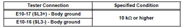


REPLACE ECM
3 INSPECT SHIFT SOLENOID VALVE SL3

(a) Remove the shift solenoid valve SL3.
(b) Measure the resistance according to the value(s) in the table below.
Standard resistance
(c) Connect the positive (+) lead with a 21 W bulb to terminal 2 and the negative (-) lead to terminal 1 of the solenoid valve connector, then check the movement of the valve.
OK: The solenoid makes an operating sound.


REPAIR OR REPLACE TRANSMISSION WIRE
 Pressure Control Solenoid "C" Performance (Shift
Solenoid Valve SL3)
Pressure Control Solenoid "C" Performance (Shift
Solenoid Valve SL3)
SYSTEM DESCRIPTION
The ECM uses signals from the vehicle speed sensor to detect the actual gear
position (1st, 2nd, 3rd, 4th
or 5th gear).
Then the ECM compares the actual gear with the shift s ...
 Shift Solenoid "D" Control Circuit
DESCRIPTION
Shifting from 1st to 5th is performed in combination with "ON" and "OFF"
operation of the shift solenoid
valves SL1, SL2, SL3, S4 and SR which are controlled by ...
Other materials:
Stowing the flat tire
Take out the strap and tire bag.
Place tire standing up in rear
tub, after putting the tire in the
tire bag.
Clip clasp to outboard hook.
Clip other clasp to center or
opposite hook location.
Pull strap to tighten and secure
tire.
...
Installation
1. Install purge vsv
(A) install the purge vsv with the bolt.
Torque: 10 n*m (102 kgf*cm, 7 ft.*Lbf)
(B) connect the 2 vacuum hoses and no. 1 Vacuum
switching valve connector.
2. INSTALL V-BANK COVER SUB-ASSEMBLY (See
page EM-63)
3. CONNECT CABLE TO NEGATIVE BATTERY
TERMINAL ...
Vehicle Position Mark is not Updated
INSPECTION PROCEDURE
1 CHECK MAP DISC
Check that the map disc is not deformed or cracked.
OK:
No deformations or cracks on map disc.
2 CHECK MAP DISPLAY
Check if a touch scroll can be performed on the map
display.
OK:
Touch scroll can be performed
3 CHECK VEHICLE SENSOR (NAV ...
