Toyota Sienna Service Manual: Rear Air Mix Damper Control Servo Motor Circuit
DESCRIPTION
The rear air mix control servo motor (water valve servo motor) is controlled by the A/C amplifier.
The rear air mix control servo motor moves the air mix damper by rotating
(normal, reverse) with electrical
power from the A/C amplifier.
WIRING DIAGRAM

INSPECTION PROCEDURE
1 READ VALUE OF INTELLIGENT TESTER
(a) Connect the intelligent tester to the DLC3.
(b) Turn the ignition switch to the ON position and turn the intelligent tester main switch on.
(c) Select the items in the DATA LIST, and read the display on the intelligent tester.
DATA LIST / AIR CONDITIONER 
OK: When the target position is "MAX. COOL" (0%), the actual opening angle is 19.0% or less.
When the target position is "MAX. HOT" (86.5%), the actual opening angle is 81.0% or more.
Result 


2 PERFORM ACTIVE TEST BY INTELLIGENT TESTER
(a) Connect the intelligent tester to the DLC3.
(b) Turn the ignition switch to the ON position and turn the intelligent tester main switch on.
(c) Select the item below in the ACTIVE TEST and then check the air flow temperature by hand.
ACTIVE TEST / AIR CONDITIONER 
OK: When the lever is moved to the "MAX. HOT" side, warm air comes out.
When the lever is moved to the "MAX. COOL" side, cool air comes out.
Result 


3 PERFORM ACTUATOR CHECK
(a) Enter the actuator check mode (See page AC-15).
(b) Press the DEF switch and change to the step operation.
(c) Check the air flow temperature by hand.

OK: Air flow temperature changes in accordance with each display code.
Result 


4 INSPECT REAR AIR MIX CONTROL SERVO MOTOR (WATER VALVE SERVO MOTOR)

(a) Remove the rear air mix control servo motor (water valve servo motor).
(b) Disconnect the connector from the rear air mix control servo motor.
(c) Connect the positive (+) lead from the battery to terminal 5 and the negative (-) lead to terminal 4, then check that the lever turns to the "MAX. COOL" position smoothly.
OK: Lever turns to "MAX. COOL" position smoothly.
(d) Connect the positive (+) lead from the battery to terminal 4 and the negative (-) lead to terminal 5, then check that the lever turns to the "MAX. HOT" position smoothly.
OK: Lever turns to "MAX. HOT" position smoothly.


5 CHECK HARNESS AND CONNECTOR (REAR AIR MIX CONTROL SERVO MOTOR - A/C AMPLIFIER)

(a) Disconnect the connector from the A/C amplifier.
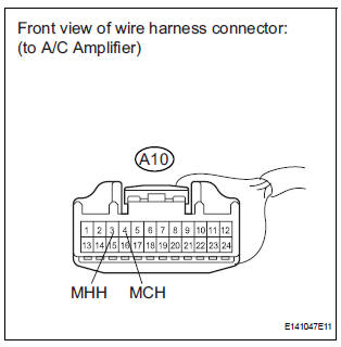
(b) Measure the resistance according to the value(s) in the table below.
Standard resistance 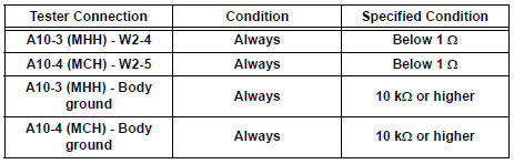


REPLACE A/C AMPLIFIER
 Air Mix Damper Control Servo Motor Circuit (Driver Side)
DESCRIPTION
The air mix control servo motor (air mix damper servo sub-assembly) is
controlled by the A/C amplifier.
The air mix control servo motor moves the air mix damper by rotating (normal, ...
 Rear Air Outlet Damper Control Servo Motor Circuit
DESCRIPTION
This circuit turns the servo motor and changes each damper position by
receiving the signals from the A/
C amplifier.
The rear air outlet damper servo motor switches the air outlet ...
Other materials:
SRS Warning Light does not Come ON
DESCRIPTION
WIRING DIAGRAM
INSPECTION PROCEDURE
1 CHECK BATTERY
Measure the voltage of the battery.
Standard voltage:
11 to 14 V
2 CHECK CONNECTORS
Turn the ignition switch to the LOCK position.
Disconnect the negative (-) terminal cable from the
battery, and wait for at le ...
Window defogger switch
INSPECTION
1. INSPECT WINDOW DEFOGGER SWITCH
Check the defogger switch illuminates.
Standard
If the result is not as specified, replace the switch
assembly or bulb.
Check the defogger timer.
Connect the positive (+) lead from the battery
to terminal 2 and ...
Short to GND in Rear Curtain Shield Squib RH
Circuit
DTC B1632/81 Short to GND in Rear Curtain Shield Squib RH
Circuit
DESCRIPTION
The rear curtain shield squib RH circuit consists of the center airbag sensor
assembly and the curtain
shield airbag assembly RH.
The circuit instructs the SRS to deploy when deployment conditions are met.
DTC ...
