Toyota Sienna Service Manual: Reassembly
1. INSTALL LIGHT CONTROL ECU (DISCHARGE HEADLIGHT)

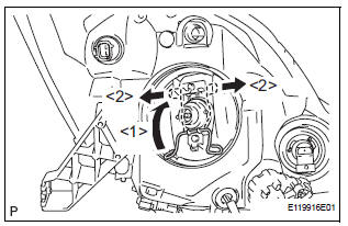
- Install a new headlight leveling motor base packing.
- Install the headlight leveling motor assembly as shown in the illustration.

- Connect the connector with the claw

- Install the light control ECU with the 2 screws.
- Install a new headlight gasket.
- Install the headlight cover with the 4 screws.
2. INSTALL FRONT SIDE MARKER LIGHT BULB

- Install the side marker light bulb to the side marker light socket
- Turn in the direction indicated by the arrow and install the side marker light bulb and side marker light socket as a unit.
3. INSTALL FRONT TURN SIGNAL LIGHT BULB

- Install the front turn signal light bulb to the front turn signal light socket.

- Turn in the direction indicated by the arrow and install the front turn signal light bulb and front turn signal light socket as a unit.
4. INSTALL NO. 2 HEADLIGHT BULB

- Turn in the direction indicated by the arrow and install the No.2 headlight bulb.
5. INSTALL DISCHARGE HEADLIGHT BULB (DISCHARGE HEADLIGHT)
- Install the discharge headlight bulb with the set spring as shown in the illustration.

- Turn in the direction indicated by the arrow and install the socket.

- Turn in the direction indicated by the arrow and install the headlight socket cover.
6. INSTALL NO. 1 HEADLIGHT BULB (HALOGEN HEADLIGHT)

- Turn in the direction indicated by the arrow and install the No.1 headlight bulb.
 Adjustment
1. VEHICLE PREPARATION FOR HEADLIGHT AIMING
ADJUSTMENT
Prepare the vehicle:
Ensure there is no damage or deformation to the
body around the headlights.
Fill the fuel t ...
 Installation
1. INSTALL HEADLIGHT ASSEMBLY
Connect the connectors.
Install the headlight assembly with the bolt and 3
screws.
2. INSTALL FRONT BUMPER ASSEMBLY
3. CONNECT CABLE TO NEGATI ...
Other materials:
Power back door drive unit
INSPECTION
1. INSPECT POWER BACK DOOR DRIVE UNIT
Remove the unit.
Apply battery voltage to the terminals and check the
motor operation.
Standard
If the result is not as specified, replace the drive
unit.
Check the resistance of the clutch terminals.
Resistance
If th ...
Front Clearance Sonar Sensor RH Circuit
DESCRIPTION
An ultrasonic sensor consists of a sensor portion that transmits and receives
ultrasonic waves and a preamplifier
that amplifies them. The ultrasonic sensor outputs the ultrasonic waves and
sends the reveiced
signals to the clearance warning ECU.
WIRING DIAGRAM
INSPECTION PR ...
Unlock warning switch
INSPECTION
1. INSPECT UNLOCK WARNING SWITCH ASSEMBLY
Remove the unlock warning switch assembly .
Measure the resistance according to the value(s) in
the table below.
Standard resistance
...
