Toyota Sienna Service Manual: Reassembly
1. INSTALL FRONT DOOR WIRE LH
- Install the wire with the 2 bolts.
Torque: Reference 8.0 N*m (82 kgf*cm, 71 in.*lbf)
NOTICE: In order to prevent water leakage, be sure that the lip of the rubber grommet does not turn up or is not deformed when installing the wire.
- Connect the wire clips.
2. INSTALL FRONT DOOR CHECK ASSEMBLY LH

- Apply MP grease to the sliding area of the door check.
- Install the door check to the door panel with the 2
nuts.
Torque: 5.5 N*m (56 kgf*cm, 49 in.*lbf) HINT: Install the door check so that the rivet head is up.
- Apply adhesive to the threads of the bolt.
Adhesive: Part No. 08833-00070, THREE BOND 1324 or equivalent
- Install the door check to the body with the bolt.
Torque: 26 N*m (265 kgf*cm, 19 ft.*lbf)
3. INSTALL FRONT DOOR OUTSIDE HANDLE FRAME SUB-ASSEMBLY LH
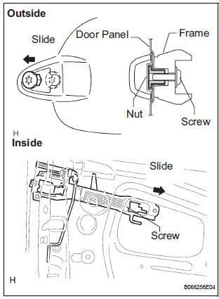
- Install the open rod to the outside handle frame.
- Slide the outside handle frame in the indicated by the arrow mark in the illustration.
- Using a torx socket wrench (T30), install the outside
handle frame with the screw.
Torque: 4.0 N*m (41 kgf*cm, 35 in.*lbf) NOTICE: Insert a cover between the nut and the door panel.
- Install the outside handle pads front and rear.
4. INSTALL FRONT DOOR HANDLE ASSEMBLY OUTSIDE LH
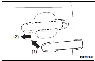
- Install the outside handle by pushing in the direction indicated by the arrow mark in the illustration.
NOTICE: If the release plate is not pulled and held when installing the outside handle, it will strike against with the outside handle and become damaged.
5. INSTALL FRONT DOOR WITH MOTOR LOCK ASSEMBLY LH
- Apply MP grease to the sliding and area of the door lock.
- Install a new door lock wire harness packing to the door lock.
NOTICE:
- When reusing a door lock that has been removed, replace the packing in the connecting part with new packing.
- Be careful that no grease or dirt sticks to the packing surface in the connecting part.
- Reusing removed packing or using damaged packing will allow water to penetrate through to the connecting part, resulting in a malfunction of the door lock.
- Insert the open rod into the lock and then set it to the door panel.
NOTICE: Make sure that the outside handle link is securely engaged with the door lock.

- Apply adhesive to the threads of the screws.
Adhesive: Part No. 08833-00070, THREE BOND 1324 or equivalent
- Using a torx socket wrench (T30), install the lock
with the 3 screws.
Torque: 5.0 N*m (51 kgf*cm, 42 in.*lbf)
- Connect the lock connector.
6. INSTALL FRONT DOOR OUTSIDE HANDLE COVER
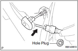
- Using a torx socket wrench (T30), install the outside
handle cover with the screw.
Torque: 4.0 N*m (41 kgf*cm, 35 in.*lbf)
- Install the hole plug.
7. INSTALL FRONT DOOR FRAME SUB-ASSEMBLY REAR LOWER LH

- Install the frame with the bolt.
Torque: 8.0 N*m (82 kgf*cm, 71 in.*lbf)
8. INSTALL POWER WINDOW REGULATOR MOTOR ASSEMBLY LH
- Using a torx driver (T25), install the regulator motor
with the 3 screws.
Torque: 5.4 N*m (55 kgf*cm, 48 in.*lbf)
HINT: Never rotate the motor assembly counterclockwise until the window glass installation is done.
9. INSTALL FRONT DOOR WINDOW REGULATOR SUBASSEMBLY LH
- Apply MP grease to the sliding and rotating parts of the window regulator.
NOTICE: Do not apply grease to the spring of the window regulator.
- Install the window regulator with 6 bolts.
Torque: 8.0 N*m (82 kgf*cm, 71 in.*lbf)
- Connect the window regulator connector.
NOTICE: Be careful not to drop the door window regulator as this may cause deformation.
10. INSTALL FRONT DOOR GLASS SUB-ASSEMBLY LH
NOTICE: Do not damage the door glass.

- Install the glass run.
- Insert the door glass into the door panel along the glass run in the direction indicated by the arrow mark in the illustration.

- Install the door glass to the window regulator with
the 2 bolts.
Torque: 5.5 N*m (56 kgf*cm, 49 in.*lbf)
- Reset the power window motor (See page WS-5).
- Inspect operation of the power window.
HINT: When the installation point of the door glass does not match, adjust the regulator position in manual operation.
- Connect the power window switch to the wire harness and turn the ignition switch ON.
- Repeat UP and DOWN operation several times in manual operation.
11. INSTALL OUTER REAR VIEW MIRROR ASSEMBLY LH

- Install the mirror with the 3 nuts.
Torque: 8.0 N*m (82 kgf*cm, 71 in.*lbf)
- Connect the mirror connector.
12. INSTALL FRONT DOOR SERVICE HOLE COVER LH
- Apply butyl tape to the door panel, as shown in the illustration.
- Install the service hole cover.
HINT:
- When installing the service hole cover, pull out the links and connectors through the service hole cover.
- There should be no wrinkles or folds after attaching the service hole cover.
- After attaching the service hole cover, confirm the sealing condition.
 Adjustment
HINT:
On the RH side, use the same procedures as on the LH
side.
Since a centering bolt is used as a door hinge mounting
bolt on the body side and the door side, the door can not
be adjust ...
 Slide door
COMPONENTS
...
Other materials:
Identification of noise source
1. Radio Description
Radio frequency band
Radio broadcasts use the radio frequency bands
shown in the table below.
Service area
The service areas of AM and FM broadcasts are
vastly different. Sometimes an AM broadcast
can be received very clearly ...
Steering Angle Sensor Communication Stop Mode
DESCRIPTION
Detection Item
Symptom
Trouble Area
Steering Angle Sensor
Communication Stop
Mode
"Steering angle sensor" is not displayed on the
"Communication Bus Check" screen of the
intelligent tester
Applies to &qu ...
DTC check / clear
HINT: If the system cannot enter the diagnostic mode,
inspect all AVC-LAN communication signals and repair or replace problem parts.
1. STARTING DIAGNOSTIC MODE
Turn the ignition switch to the ACC position.
Turn off the audio system.
While pressing the preset switche ...
