Toyota Sienna Service Manual: Removal
1. Remove windshield wiper motor assembly hint: (see page ww-4) 2. Remove front outer cowl top panel subassembly (see page em-27) 3. Drain engine coolant (see page co-6) 4. Remove v-bank cover sub-assembly (see page em-28) 5. Remove no. 2 Air cleaner inlet (see page em- 28) 6. Remove no. 1 Air cleaner inlet (see page em- 28) 7. Remove air cleaner cap sub-assembly
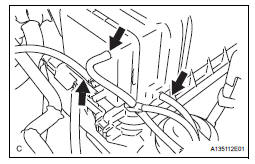
(A) disconnect the 3 vacuum hoses.

(b) Remove the No. 2 ventilation hose and air cleaner hose band.
(c) Disconnect the vacuum hose (EVAP) from the air cleaner hose.
(d) Disconnect the mass air flow meter connector.
(e) Remove the 2 bolts and air cleaner cap subassembly.
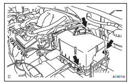
8. REMOVE AIR CLEANER CASE SUB-ASSEMBLY (See page EM-28)
9. REMOVE THROTTLE BODY

(a) Disconnect the throttle body connector and clamp.

(b) Disconnect the 2 water by-pass hoses from the throttle body.

(c) Remove the 4 bolts and throttle body.
(d) Remove the throttle body gasket from the intake air surge tank.
INSPECTION
1. INSPECT THROTTLE BODY

(a) Using an ohmmeter, measure the resistance between the terminals.
Standard resistance

If the result is not as specified, replace the throttle body assembly.
 On-vehicle inspection
1. INSPECT THROTTLE BODY
(a) Listen to the throttle control motor operating sounds.
(1) Turn the ignition switch to the ON position.
(2) When pressing the accelerator pedal position
sensor lever ...
 Installation
1. INSTALL THROTTLE BODY
(a) Install a new throttle body gasket to the intake air
surge tank.
(b) Install the throttle body with the 4 bolts.
Torque: 10 N*m (102 kgf*cm, 7 ft.*lbf)
...
Other materials:
Diagnosis system
1. DESCRIPTION
When troubleshooting OBD II (On-Board
Diagnostics) vehicles, an intelligent tester
(complying with SAE J1987) must be connected to
the DLC3 (Data Link Connector 3) of the vehicle.
Various data in the vehicle's ECM (Engine Control
Module) can be then read.
& ...
Actuator Supply Voltage Circuit / Open
DESCRIPTION
The ECM monitors the output voltage to the throttle actuator. This self-check
ensures that the ECM is
functioning properly. The output voltage is usually 0 V when the ignition switch
is turned off. If the output
voltage is higher than 7 volts when the ignition switch is turned ...
Cooling fan relay
On-vehicle inspection
1. Cooling fan relay
(a) Remove the relay from engine room relay block No.
1.
(b) Measure the resistance of the relay.
Standard resistance
If the result is not as specified, replace the cooling
fan relay.
(c) Install the relay to engine room relay block No. ...
