Toyota Sienna Service Manual: Seat Belt Buckle Switch LH Circuit Malfunction
DTC B0126/27 Seat Belt Buckle Switch LH Circuit Malfunction
DESCRIPTION
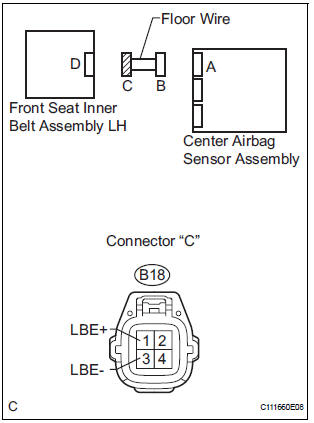
The seat belt buckle switch LH circuit consists of the center airbag sensor assembly and the front seat inner belt assembly LH.
DTC B0126/27 is recorded when a malfunction is detected in the seat belt buckle switch LH circuit
|
DTC No. |
DTC Detecting Condition |
Trouble Area |
|
B0126/27 |
|
|
WIRING DIAGRAM

INSPECTION PROCEDURE
1 CHECK DTC

- Turn the ignition switch to the ON position, and wait for at least 60 seconds.
- Clear the DTCs stored in memory (5).
- Turn the ignition switch to the LOCK position.
- Turn the ignition switch to the ON position, and wait for at least 60 seconds.
- Check the DTCs (5).
OK: DTC B0126/27 is not output. HINT: Codes other than code B0126/27 may be output at this time, but they are not related to this check.
 Go to step 2

USE SIMULATION METHOD TO CHECK
2 CHECK CONNECTION OF CONNECTORS
- Turn the ignition switch to the LOCK position.
- Disconnect the negative (-) terminal cable from the battery, and wait for at least 90 seconds.
- Check that the connectors are properly connected to the center airbag sensor assembly and the front seat inner belt assembly LH.
OK: The connectors are connected.
 CONNECT CONNECTORS

3 CHECK VEHICLE
- Check the front driver seat type.
Result

 Go to step 11
4 CHECK FLOOR WIRE (OPEN)

- Disconnect the connectors from the center airbag sensor assembly and the front seat inner belt assembly LH.
- w/ Side airbag:
Using a service wire, connect A20-19 (LBE+) and A20-2
(LBE-) of connector "B".
NOTICE: Do not forcibly insert a service wire into the terminals of the connector when connecting.
- w/o Side airbag:
Using a service wire, connect A20-11 (LBE+) and A20-6
(LBE-) of connector "B".
NOTICE: Do not forcibly insert a service wire into the terminals of the connector when connecting.
- Measure the resistance according to the value(s) in the table below.
Standard resistance

 REPAIR OR REPLACE FLOOR WIRE

5 CHECK FLOOR WIRE (SHORT TO B+)

- Disconnect the service wire from connector "B".
- Connect the negative (-) terminal cable to the battery, and wait for at least 2 seconds.
- Turn the ignition switch to the ON position.
- Measure the voltage according to the value(s) in the table below.
Standard voltage

 REPAIR OR REPLACE FLOOR WIRE

6 CHECK FLOOR WIRE (SHORT TO GROUND)

- Turn the ignition switch to the LOCK position.
- Disconnect the negative (-) terminal cable from the battery, and wait for at least 90 seconds.
- Measure the resistance according to the value(s) in the table below.
Standard resistance

 REPAIR OR REPLACE FLOOR WIRE

7 CHECK FLOOR WIRE (SHORT)

- Measure the voltage according to the value(s) in the table below.
Standard resistance

 REPAIR OR REPLACE FLOOR WIRE

8 CHECK FRONT SEAT INNER BELT ASSEMBLY LH

- Connect the connectors to the front seat inner belt assembly LH and the center airbag sensor assembly.
- Connect the negative (-) terminal cable to the battery, and wait for at least 2 seconds.
- Turn the ignition switch to the ON position, and wait for at least 60 seconds.
- Clear the DTCs stored in memory (5).
- Turn the ignition switch to the LOCK position.
- Turn the ignition switch to the ON position, and wait for at least 60 seconds.
- Check the DTCs (5).
OK: DTC B0126/27 is not output. HINT: Codes other than code B0126/27 may be output at this time, but they are not related to this check.
 Go to step 9

USE SIMULATION METHOD TO CHECK
9 REPLACE FRONT SEAT INNER BELT ASSEMBLY LH
- Turn the ignition switch to the LOCK position.
- Disconnect the negative (-) terminal cable from the battery, and wait for at least 90 seconds.
- Replace the front seat inner belt assembly LH.
HINT: Perform the inspection using parts from a normal vehicle if possible.

10 CHECK CENTER AIRBAG SENSOR ASSEMBLY

- Connect the negative (-) terminal cable to the battery, and wait for at least 2 seconds.
- Turn the ignition switch to the ON position, and wait for at least 60 seconds.
- Clear the DTCs stored in memory (5).
- Turn the ignition switch to the LOCK position.
- Turn the ignition switch to the ON position, and wait for at least 60 seconds.
- Check the DTCs (5).
OK: DTC B0126/27 is output. HINT: Codes other than code B0126/27 may be output at this time, but they are not related to this check.
 REPLACE CENTER AIRBAG SENSOR
ASSEMBLY
REPLACE CENTER AIRBAG SENSOR
ASSEMBLY

END
11 CHECK FLOOR WIRE (OPEN)

- Disconnect the connectors from the center airbag sensor assembly and the front seat inner belt assembly LH.
- w/ Side airbag:
Using a service wire, connect A20-19 (LBE+) and A20-2
(LBE-) of connector "B".
NOTICE: Do not forcibly insert a service wire into the terminals of the connector when connecting.
- w/o Side airbag:
Using a service wire, connect A20-11 (LBE+) and A20-6
(LBE-) of connector "B".
NOTICE: Do not forcibly insert a service wire into the terminals of the connector when connecting.
- Measure the resistance according to the value(s) in the table below.
Standard resistance

 REPAIR OR REPLACE FLOOR WIRE

12 CHECK FLOOR WIRE (SHORT TO B+)
- Disconnect the service wire from connector "B".
- Connect the negative (-) terminal cable to the battery, and wait for at least 2 seconds.
- Turn the ignition switch to the ON position.
- Measure the voltage according to the value(s) in the table below.
Standard voltage

 REPAIR OR REPLACE FLOOR WIRE

13 CHECK FLOOR WIRE (SHORT TO GROUND)

- Turn the ignition switch to the LOCK position.
- Disconnect the negative (-) terminal cable from the battery, and wait for at least 90 seconds.
- Measure the resistance according to the value(s) in the table below.
Standard resistance

 REPAIR OR REPLACE FLOOR WIRE

14 CHECK FLOOR WIRE (SHORT)

- Measure the resistance according to the value(s) in the table below.
Standard resistance

 REPAIR OR REPLACE FLOOR WIRE

15 CHECK FRONT SEAT INNER BELT ASSEMBLY LH

- Connect the connectors to the front seat inner belt assembly LH and the center airbag sensor assembly.
- Connect the negative (-) terminal cable to the battery, and wait for at least 2 seconds.
- Turn the ignition switch to the ON position, and wait for at least 60 seconds.
- Clear the DTCs stored in memory (5).
- Turn the ignition switch to the LOCK position.
- Turn the ignition switch to the ON position, and wait for at least 60 seconds.
- Check the DTCs (5).
OK: DTC B0126/27 is not output. HINT: Codes other than code B0126/27 may be output at this time, but they are not related to this check.
 Go to step 16

USE SIMULATION METHOD TO CHECK
16 REPLACE FRONT SEAT INNER BELT ASSEMBLY LH
- Turn the ignition switch to the LOCK position.
- Disconnect the negative (-) terminal cable from the battery, and wait for at least 90 seconds.
- Replace the front seat inner belt assembly LH.
HINT: Perform the inspection using parts from a normal vehicle if possible.

17 CHECK CENTER AIRBAG SENSOR ASSEMBLY

- Connect the negative (-) terminal cable to the battery, and wait for at least 2 seconds.
- Turn the ignition switch to the ON position, and wait for at least 60 seconds.
- Clear the DTCs stored in memory (5).
- Turn the ignition switch to the LOCK position.
- Turn the ignition switch to the ON position, and wait for at least 60 seconds.
- Check the DTCs (5).
OK: DTC B0126/27 is not output. HINT: Codes other than code B0126/27 may be output at this time, but they are not related to this check.
 REPLACE CENTER AIRBAG SENSOR
ASSEMBLY
REPLACE CENTER AIRBAG SENSOR
ASSEMBLY

END
 Short to B+ in Side Squib LH Circuit
DTC B0118/46 Short to B+ in Side Squib LH Circuit
DESCRIPTION
The side squib LH circuit consists of the center airbag sensor assembly and
the front seat side airbag
assembly LH (side squib LH).
...
 Short in Front Pretensioner Squib RH Circuit
DTC B0130/63 Short in Front Pretensioner Squib RH Circuit
DESCRIPTION
The front pretensioner squib RH circuit consists of the center airbag sensor
assembly and the front seat
outer belt assembly ...
Other materials:
Brake control
Sst
Recommended tools
HINT:
Torx is a registered trademark of Textron Inc.
EQUIPMENT
LUBRICANT
BRAKE
SST
RECOMMENDED TOOLS
EQUIPMENT
LUBRICANT
PARKING BRAKE
EQUIPMENT
STEERING COLUMN
SST
EQUIPMENT
...
Disassembly
1. FIX FRONT SHOCK ABSORBER WITH COIL SPRING
(a) Install 2 nuts and a bolt to the bracket at the lower
side of the front shock absorber with coil spring and
secure it in a vise.
2. REMOVE FRONT SUSPENSION SUPPORT SUBASSEMBLY LH
(a) Using SST, compress the front coil spring LH
SST 09727-300 ...
No. 2 Ultrasonic sensor
COMPONENTS
REMOVAL
1. REMOVE REAR BUMPER COVER (2)
2. REMOVE NO. 1 ULTRASONIC SENSOR RETAINER
Remove the No. 1 ultrasonic sensor retainer as
shown in the illustration
3. REMOVE NO. 2 ULTRASONIC SENSOR
Disconnect the connector and remove the No. 2
ultrasonic ...
