Toyota Sienna Service Manual: Short in Front Passenger Side Squib Circuit
DTC B0105/53 Short in Front Passenger Side Squib Circuit
DESCRIPTION
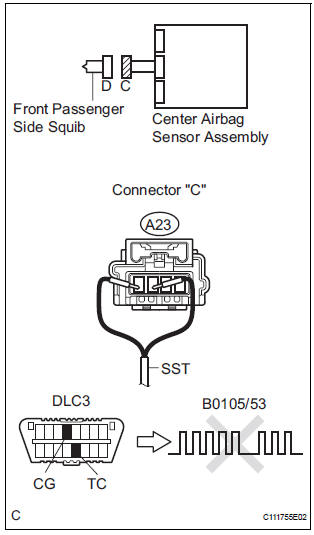
The front passenger side squib circuit consists of the center airbag sensor assembly and the front passenger airbag assembly.
The circuit instructs the SRS to deploy when deployment conditions are met.
DTC B0105/53 is recorded when a short circuit is detected in the front passenger side squib circuit.

WIRING DIAGRAM

INSPECTION PROCEDURE
HINT:
- Perform the simulation method by selecting the "check mode" (signal check) with the intelligent tester
- After selecting the "check mode" (signal check), perform the simulation method by wiggling each connector of the airbag system or driving the vehicle on a city or rough road
1 CHECK FRONT PASSENGER AIRBAG ASSEMBLY (FRONT PASSENGER SIDE SQUIB)
- Turn the ignition switch to the LOCK position.
- Disconnect the negative (-) terminal cable from the battery, and wait for at least 90 seconds.
- Disconnect the connectors from the front passenger airbag assembly.
- Connect the black wire side of SST (resistance 2.1 Ω) to the instrument panel wire.
CAUTION: Never connect a tester to the front passenger airbag assembly (front passenger side squib) for measurement, as this may lead to a serious injury due to airbag deployment.
NOTICE: Do not forcibly insert the SST into the terminals of the connector when connecting.
Insert the SST straight into the terminals of the connector.
SST 09843-18060
- Connect the negative (-) terminal cable to the battery, and wait for at least 2 seconds.
- Turn the ignition switch to the ON position, and wait for at least 60 seconds.
- Clear the DTCs stored in memory.
- Turn the ignition switch to the LOCK position.
- Turn the ignition switch to the ON position, and wait for at least 60 seconds.
- Check the DTCs.
OK: DTC B0105/53 is not output.
HINT: Codes other than DTC B0105/53 may be output at this time, but they are not related to this check.
REPLACE FRONT PASSENGER AIRBAG ASSEMBLY
2 CHECK INSTRUMENT PANEL WIRE (FRONT PASSENGER SIDE SQUIB CIRCUIT)

- Turn the ignition switch to the LOCK position.
- Disconnect the negative (-) terminal cable from the battery, and wait for at least 90 seconds.
- Disconnect the SST (resistance 2.1 Ω) from the instrument panel wire.
- Disconnect the connector from the center airbag sensor assembly.
- Release the activation prevention mechanism built into connector "B".
- Measure the resistance according to the value(s) in the table below.
Standard resistance

3 CHECK CENTER AIRBAG SENSOR ASSEMBLY

- Connect the connectors to the front passenger airbag assembly and the center airbag sensor assembly.
- Connect the negative (-) terminal cable to the battery, and wait for at least 2 seconds.
- Turn the ignition switch to the ON position, and wait for at least 60 seconds.
- Clear the DTCs stored in memory.
- Turn the ignition switch to the LOCK position.
- Turn the ignition switch to the ON position, and wait for at least 60 seconds.
- Check the DTCs.
OK: DTC B0105/53 is not output.
HINT: Codes other than code B0105/53 may be output at this time, but they are not related to this check.
USE SIMULATION METHOD TO CHECK
 Short to B+ in Driver Side Squib Circuit
DTC B0103/12 Short to B+ in Driver Side Squib Circuit
DESCRIPTION
The driver side squib circuit consists of the center airbag sensor assembly,
the spiral cable and the
steering pad.
The circui ...
 Open in Front Passenger Side Squib Circuit
DTC B0106/54 Open in Front Passenger Side Squib Circuit
DESCRIPTION
The front passenger side squib circuit consists of the center airbag sensor
assembly and the front
passenger airbag assembly.
...
Other materials:
DTC check / clear
HINT: If the system cannot enter the diagnostic mode,
inspect all AVC-LAN communication signals and repair or replace problem parts.
1. STARTING DIAGNOSTIC MODE
Turn the ignition switch to the ACC position.
Turn off the audio system.
While pressing the preset switche ...
Operation check
1. ILLUMINATED ENTRY SYSTEM OPERATION CHECK
The illuminated entry system is explained below:
Turn the ignition switch OFF, close all the doors,
and set them in the lock condition.
Unlock any door and open any other doors and
check that the room light comes on. Close ...
Installation
1. INSTALL REAR DOOR WINDOW FRAME MOULDING
Remove the tape from the rear door window frame
moulding.
Clean the contact surface of the vehicle body with
white gasoline.
Clean the outer circumference of the rear door
window frame moulding with white gasoline.
Apply new double-sided ...
