Toyota Sienna Service Manual: Short to B+ in Door System Communication Bus Malfunction/ Short to GND in Door System Communication Bus Malfunction
DTC B1214 Short to B+ in Door System Communication Bus Malfunction
DTC B1215 Short to GND in Door System Communication Bus Malfunction
DESCRIPTION
DTCs B1214 and B1215 are output when a short to +B or the body ground occurs on the communication bus. Detecting this condition disables all the BEAN communication and outputs some DTCs.
|
DTC No. |
DTC Detection Condition |
Trouble Area |
|
B1214 |
Communication circuit and +B battery system short |
|
|
B1215 |
Communication circuit and body ground short |
|
WIRING DIAGRAM

INSPECTION PROCEDURE
NOTICE: Disconnect connectors in operational sequence, and start the next operation after the connectors are connected
1 CHECK DTC (MULTIPLEX NETWORK BODY ECU - COMBINATION METER)
- Check the DTC when the B7 connector of the multiplex network body ECU and the combination meter connector are disconnected.

OK: DTC B1214 or B1215 is not output.
HINT: When the output of the DTC stops, there is a malfunction between the B7 connector of the multiplex network body ECU and the combination meter.
2 CHECK DTC (COMBINATION METER)
- Check whether the output of the DTC stops when the combination meter connector is disconnected.

OK: DTC B1214 or B1215 is not output.
HINT: When the output of the DTC stops, the combination meter is malfunctioning.
3 CHECK DTC (A/C AMPLIFIER)
- Check whether the output of the DTC stops when the A/ C amplifier connector is disconnected.

OK: DTC B1214 or B1215 is not output.
HINT: When the output of the DTC stops, the A/C amplifier is malfunctioning.
4 CHECK HARNESS AND CONNECTOR (COMBINATION METER - A/C AMPLIFIER)
- Check whether the output of the DTC stops when the combination meter connector and the A/C amplifier connector are disconnected.

OK: DTC B1214 or B1215 is not output.
HINT: When the output of the DTC stops, the wire harness between the combination meter and the A/C amplifier is malfunctioning.
5 CHECK DTC (AIRBAG SENSOR ASSEMBLY)
- Check whether the output of the DTC stops when the airbag sensor assembly connector is disconnected.
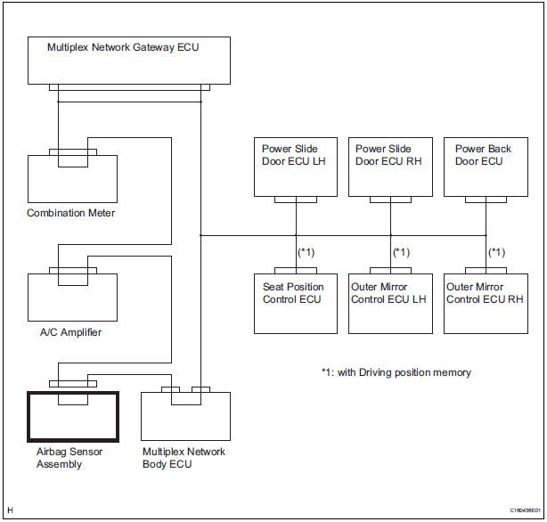
OK: DTC B1214 or B1215 is not output.
HINT: When the output of the DTC stops, the airbag sensor assembly is malfunctioning.
6 CHECK HARNESS AND CONNECTOR (A/C AMPLIFIER - AIRBAG SENSOR ASSEMBLY)
- Check whether the output of the DTC stops when the A/ C amplifier connector and the airbag sensor assembly connector are disconnected.

OK: DTC B1214 or B1215 is not output.
HINT: When the output of the DTC stops, the wire harness between the A/C amplifier and airbag sensor assembly is malfunctioning.
7 CHECK DTC (MULTIPLEX NETWORK BODY ECU)
- Check whether the output of the DTC stops when the B7 and 1E connectors of the multiplex network body ECU are disconnected.

OK: DTC B1214 or B1215 is not output.
HINT: When the output of the DTC stops, the multiplex network body ECU is malfunctioning.
REPAIR OR REPLACE HARNESS OR CONNECTOR (AIRBAG SENSOR ASSEMBLY - MULTIPLEX NETWORK BODY ECU)
8 CHECK DTC (POWER SLIDE DOOR ECU LH)
- Check whether the output of the DTC stops when the power slide door ECU LH connector is disconnected.

OK: DTC B1214 or B1215 is not output.
HINT: When the output of the DTC stops, the power slide door ECU LH is malfunctioning
9 CHECK DTC (POWER SLIDE DOOR ECU RH)
- Check whether the output of the DTC stops when the power slide door ECU RH connector is disconnected.

OK: DTC B1214 or B1215 is not output.
HINT: When the output of the DTC stops, the power slide door ECU RH is malfunctioning.
10 CHECK DTC (POWER BACK DOOR ECU)
- Check whether the output of the DTC stops when the power back door ECU connector is disconnected.

OK: DTC B1214 or B1215 is not output.
HINT: When the output of the DTC stops, the power back door ECU is malfunctioning.
11 CONFIRM MODEL
Result

12 CHECK DTC (SEAT POSITION CONTROL ECU)
- Check whether the output of the DTC stops when the seat position control ECU connector is disconnected.

OK: DTC B1214 or B1215 is not output.
HINT: When the output of the DTC stops, the seat position control ECU is malfunctioning.
13 CHECK DTC (OUTER MIRROR CONTROL ECU LH)
- Check whether the output of the DTC stops when the outer mirror control ECU LH connector is disconnected.
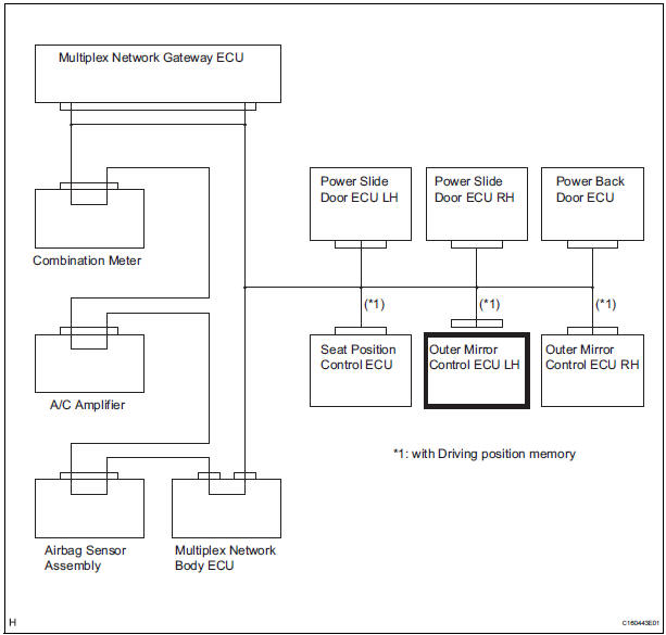
OK: DTC B1214 or B1215 is not output.
HINT: When the output of the DTC stops, the outer mirror control ECU LH is malfunctioning.
14 CHECK DTC (OUTER MIRROR CONTROL ECU RH)
- Check whether the output of the DTC stops when the outer mirror control ECU RH connector is disconnected.

OK: DTC B1214 or B1215 is not output.
HINT: When the output of the DTC stops, the outer mirror control ECU RH is malfunctioning.
15 CHECK HARNESS AND CONNECTOR
- Check for a short to +B or body ground.
- Disconnect the multiplex network gateway ECU, combination meter, power slide door ECU LH, power slide door ECU RH, power back door ECU, seat position control ECU (*1), outer mirror control ECU LH (*1), outer mirror control ECU RH (*1) and the B7 connector of the multiplex network body ECU.

HINT: *1: with Driving position memory
- Measure the voltage according to the value(s) in the table below.
Standard voltage


HINT: *1: with Driving position memory
- Measure the resistance according to the value(s) in the table below.
Standard resistance

HINT: *1: with Driving position memory
REPLACE MULTIPLEX NETWORK GATEWAY ECU
 Driver Side Outer Mirror
DTC B1209 Driver Side Outer Mirror
DESCRIPTION
This DTC is detected when communication between the outer mirror control ECU
LH and multiplex
network gateway ECU stops for more than 10 seconds
...
 Rear Door ECU RH Communication Stop
DTC B1216 Rear Door ECU RH Communication Stop
DESCRIPTION
DTC B1216 is output when communication between the power slide door ECU RH
and the multiplex
network gateway ECU stops for more than 10 s ...
Other materials:
Rear Speed Sensor RH Circuit
DESCRIPTION
Refer to DTCs C0200/31, C0205/32, C1235/35, and C1236/36 (See page BC-17).
DTCs C1273/73 to C1278/78 can be deleted when the speed sensor sends a vehicle
speed signal or the
Test Mode ends. DTCs C1273/73 to C1278/78 are output only in the Test Mode.
HINT:
DTC C0210/33 ...
Removal
1. REMOVE FRONT WHEELS
2. REMOVE FRONT STABILIZER LINK ASSEMBLY LH
HINT:
(See page SP-26)
3. REMOVE FRONT STABILIZER LINK ASSEMBLY RH
HINT:
Remove the RH side by the same procedures as the LH
side.
4. REMOVE CENTER EXHAUST PIPE ASSEMBLY
HINT:
(See page EX-8)
5. REMOVE NO. 1 FRONT STABILIZ ...
Removal
1. PRECAUTION
HINT:
See page RS-1
2. DISCONNECT BATTERY NEGATIVE TERMINAL
Wait for 90 seconds after disconnecting the battery
terminal to prevent the airbag working.
3. PLACE FRONT WHEELS FACING STRAIGHT AHEAD
4. REMOVE STEERING WHEEL COVER LOWER NO.2
(See page RS-424)
5. REMOVE STEERING WH ...
