Toyota Sienna Service Manual: Short to GND in Curtain Shield Squib LH Circuit
DTC B1167/85 Short to GND in Curtain Shield Squib LH Circuit
DESCRIPTION
The curtain shield squib LH circuit consists of the center airbag sensor assembly and the curtain shield airbag assembly LH.
The circuit instructs the SRS to deploy when deployment conditions are met.
DTC B1167/85 is recorded when a short to ground is detected in the curtain shield squib LH circuit.

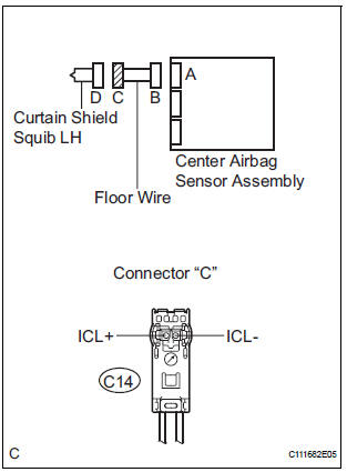
WIRING DIAGRAM
INSPECTION PROCEDURE
HINT:
- Perform the simulation method by selecting the "check mode" (signal check) with the intelligent tester.
- After selecting the "check mode" (signal check), perform the simulation method by wiggling each connector of the airbag system or driving the vehicle on a city or rough road
1 CHECK CURTAIN SHIELD AIRBAG ASSEMBLY LH (CURTAIN SHIELD SQUIB LH)

- Turn the ignition switch to the LOCK position.
- Disconnect the negative (-) terminal cable from the battery, and wait for at least 90 seconds.
- Disconnect the connectors from the curtain shield airbag assembly LH.
- Connect the white wire side of SST (resistance 2.1 Ω) to
the floor wire.
CAUTION: Never connect a tester to the curtain shield airbag assembly LH (curtain shield squib LH) for measurement, as this may lead to a serious injury due to airbag deployment.
NOTICE: Do not forcibly insert the SST into the terminals of the connector when connecting.
Insert the SST straight into the terminals of the connector.
SST 09843-18060
- Connect the negative (-) terminal cable to the battery, and wait for at least 2 seconds.
- Turn the ignition switch to the ON position, and wait for at least 60 seconds.
- Clear the DTCs stored in memory.
- Turn the ignition switch to the LOCK position.
- Turn the ignition switch to the ON position, and wait for at least 60 seconds.
- Check the DTCs
OK: DTC B1167/85 is not output.
HINT: Codes other than DTC B1167/85 may be output at this time, but they are not related to this check.
REPLACE CURTAIN SHIELD AIRBAG ASSEMBLY LH
2 CHECK FLOOR WIRE (CURTAIN SHIELD SQUIB LH CIRCUIT)
- Turn the ignition switch to the LOCK position.
- Disconnect the negative (-) terminal cable from the battery, and wait for at least 90 seconds.
- Disconnect the SST (resistance 2.1 Ω) from the floor wire.
- Disconnect the connector from the center airbag sensor assembly.
- Measure the resistance according to the value(s) in the table below.
Standard resistance

3 CHECK CENTER AIRBAG SENSOR ASSEMBLY

- Connect the connectors to the curtain shield airbag assembly LH and the center airbag sensor assembly.
- Connect the negative (-) terminal cable to the battery, and wait for at least 2 seconds.
- Turn the ignition switch to the ON position, and wait for at least 60 seconds.
- Clear the DTCs stored in memory.
- Turn the ignition switch to the LOCK position.
- Turn the ignition switch to the ON position, and wait for at least 60 seconds.
- Check the DTCs.
OK: DTC B1167/85 is not output.
HINT: Codes other than code B1167/85 may be output at this time, but they are not related to this check.
USE SIMULATION METHOD TO CHECK
 Open in Curtain Shield Squib LH Circuit
DTC B1166/88 Open in Curtain Shield Squib LH Circuit
DESCRIPTION
The curtain shield squib LH circuit consists of the center airbag sensor
assembly and the curtain shield
airbag assembly LH.
Th ...
 Short to B+ in Curtain Shield Squib LH Circuit
DTC B1168/86 Short to B+ in Curtain Shield Squib LH Circuit
DESCRIPTION
The curtain shield squib LH circuit consists of the center airbag sensor
assembly and the curtain shield
airbag assembly LH ...
Other materials:
Door Courtesy Switch Circuit
DESCRIPTION
The Multiplex network body ECU detects the condition of the door courtesy
switch assembly.
WIRING DIAGRAM
INSPECTION PROCEDURE
1 READ VALUE OF INTELLIGENT TESTER
Connect the intelligent tester to DLC3.
Turn the ignition switch to ON and push the intelligent
tester ...
Sliding doors
Vehicles without power sliding doors
The sliding doors can be opened and closed using the sliding
door handle. The sliding door can be locked and unlocked using
the wireless remote control, door lock switch or inside lock
knob.
Vehicles with power sliding doors
...
Active Control Engine Mount System
DESCRIPTION
LOCATION
The Active Control Engine Mount (ACM) system decreases engine vibration at
engine idling using the
ACM VSV. The VSV is controlled by a pulse signal transmitted to the VSV from the
ECM. The frequency
of this pulse signal is matched to the engine speed to decrease engine ...
