Toyota Sienna Service Manual: Side Airbag Sensor Assembly RH Circuit Malfunction
DTC B1140/32 Side Airbag Sensor Assembly RH Circuit Malfunction
DESCRIPTION
The side airbag sensor RH circuit consists of the center airbag sensor assembly and side airbag sensor RH.
If the center airbag sensor assembly receives signals from the side airbag sensor RH, it judges whether or not the SRS should be activated.
DTC B1140/32 is recorded when a malfunction in the side airbag sensor RH circuit is detected.
|
DTC No. |
DTC Detecting Condition |
Trouble Area |
|
B1140/32 |
|
|
WIRING DIAGRAM

INSPECTION PROCEDURE
1 CHECK DTC

- Turn the ignition switch to the ON position, and wait for at least 60 seconds.
- Clear the DTCs stored in memory (5).
- Turn the ignition switch to the LOCK position.
- Turn the ignition switch to the ON position, and wait for at least 60 seconds.
- Check the DTCs (5).
OK: DTC B1140/32 is not output. HINT: Codes other than DTC B1140/32 may be output at this time, but they are not related to this check.
 Go to step 2

USE SIMULATION METHOD TO CHECK
2 CHECK CONNECTION OF CONNECTORS
- Turn the ignition switch to the LOCK position.
- ) Disconnect the negative (-) terminal cable from the battery, and wait for at least 90 seconds.
- ) Check that the connectors are properly connected to the center airbag sensor assembly and the side airbag sensor RH.
OK: The connectors are connected.
 CONNECT CONNECTORS

3 CHECK FLOOR WIRE NO. 2 (OPEN)

- Disconnect the connectors from the center airbag sensor assembly and the side airbag sensor RH.
- Using a service wire, connect A22-17 (VUPR) and A22-
15 (ESR) of connector "B".
NOTICE: Do not forcibly insert a service wire into the terminals of the connector when connecting.
- Measure the resistance according to the value(s) in the table below.
Standard resistance


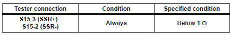
- Using a service wire, connect A22-16 (SSR+) and A22-
13 (SSR-) of connector "B".
NOTICE: Do not forcibly insert a service wire into the terminals of the connector when connecting.
- Measure the resistance according to the value(s) in the table below.
Standard resistance
 REPAIR OR REPLACE FLOOR WIRE
NO. 2
REPAIR OR REPLACE FLOOR WIRE
NO. 2

4 CHECK FLOOR WIRE NO. 2 (SHORT TO B+)

- Disconnect the service wire from connector "B".
- Connect the negative (-) terminal cable to the battery, and wait for at least 2 seconds.
- Turn the ignition switch to the ON position.
- Measure the voltage according to the value(s) in the table below.
Standard voltage

 REPAIR OR REPLACE FLOOR WIRE
NO. 2
REPAIR OR REPLACE FLOOR WIRE
NO. 2

5 CHECK FLOOR WIRE NO. 2 (SHORT TO GROUND)

- Turn the ignition switch to the LOCK position.
- Disconnect the negative (-) terminal cable from the battery, and wait for at least 90 seconds.
- Measure the resistance according to the value(s) in the table below.
Standard resistance

 REPAIR OR REPLACE FLOOR WIRE
NO. 2
REPAIR OR REPLACE FLOOR WIRE
NO. 2

6 CHECK FLOOR WIRE NO. 2 (SHORT)

- Measure the resistance according to the value(s) in the table below.
Standard resistance

 REPAIR OR REPLACE FLOOR WIRE
NO. 2
REPAIR OR REPLACE FLOOR WIRE
NO. 2

7 CHECK SIDE AIRBAG SENSOR RH

- Connect the connector to the center airbag sensor assembly.
- Interchange the side airbag sensor RH with LH and connect the connectors to them.
- Connect the negative (-) terminal cable to the battery, and wait for at least 2 seconds.
- Turn the ignition switch to the ON position, and wait for at least 60 seconds.
- Clear the DTCs stored in memory (5).
- Turn the ignition switch to the LOCK position.
- Turn the ignition switch to the ON position, and wait for at least 60 seconds.
- Check the DTCs (5).
Result

HINT: Codes other than DTC B1140/32 and B1141/33 may be output at this time, but they are not related to this check
 REPLACE CENTER AIRBAG SENSOR
ASSEMBLY
REPLACE CENTER AIRBAG SENSOR
ASSEMBLY
 REPLACE SIDE AIRBAG SENSOR
RH
REPLACE SIDE AIRBAG SENSOR
RH

USE SIMULATION METHOD TO CHECK
 Half Connection in Center Airbag Sensor
Assembly Connectors
Half Connection in Center Airbag Sensor
Assembly Connectors
DTC B1135/24 Half Connection in Center Airbag Sensor
Assembly Connectors
DESCRIPTION
The center airbag sensor assembly connector has a mechanism that electrically
detects half connection.
The ...
 Side Airbag Sensor Assembly LH Circuit Malfunction
DTC B1141/33 Side Airbag Sensor Assembly LH Circuit Malfunction
DESCRIPTION
The side airbag sensor LH circuit consists of the center airbag sensor
assembly and side airbag sensor
LH.
If the ce ...
Other materials:
Unlock warning switch
INSPECTION
1. INSPECT UNLOCK WARNING SWITCH ASSEMBLY
Remove the unlock warning switch assembly .
Measure the resistance according to the value(s) in
the table below.
Standard resistance
...
Drive shaft
SST
RECOMMENDED TOOLS
HINT:
Torx is a registered trademark of Textron Inc.
EQUIPMENT
LUBRICANT
...
Disassembly
1. REMOVE FRONT DIFFERENTIAL RING GEAR
(a) Place matchmarks on the front differential ring gear
and differential case.
(b) Remove the 14 bolts.
(c) Using a plastic hammer, tap on the front differential
ring gear to remove it from the case.
2. REMOVE FRONT DIFFERENTIAL CASE FRONT TA ...
