Toyota Sienna 2010-2024 Owners Manual: Smart key system
The following operations can be performed simply by carrying the electronic key on your person, for example in your pocket.
The driver should always carry the electronic key.
- Locks and unlocks the doors
- Front door handles
- Sliding door handles
- Back door
- Starts and stops the engine
Antenna location
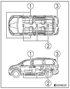
- Antennas outside cabin
- Antennas inside cabin
- Antenna outside luggage compartment
Effective range (areas within which the electronic key is detected)
 When locking or unlocking the
doors
The system can be operated when
the electronic key is within about
2.3 ft. (0.7 m) of either of the front outside
door handles. (Only the doors
detecting the key can be operated.)
 When starting the engine or
changing
engine switch modes
The system can be operated when the electronic key is inside the vehicle.
Alarms and warning indicators
An alarm sounds and warning messages are displayed on the multi-information display are used to protect against unexpected accidents or theft of the vehicle resulting from erroneous operation. When a warning message is displayed, take appropriate measures based on the displayed message.
When only an alarm sounds, circumstances and correction procedures are as follows.
|
Alarm |
Situation |
Correction procedure |
| Exterior alarm sounds once for 10 seconds | An attempt was made to lock the vehicle while a door is open | Close all of the doors and lock the doors again |
| Interior alarm pings continuously | The engine switch was turned to ACCESSORY mode while the driver’s door was open (or the driver’s door was opened while the engine switch was in ACCESSORY mode) | Turn the engine switch off and close the driver’s door |
Battery-saving function
In the following circumstances, the entry function is disabled in order to prevent the vehicle battery from discharging and the electronic key battery from discharging.
- When the entry function has not been used for 5 days or more
- When the electronic key has been left within approximately 6 ft. (2 m) of the vehicle for 10 minutes or more
- If the entry function has not been used for 14 days or more, the vehicle
cannot
be unlocked by a door other than the driver’s door. To unlock the vehicle,
grip the driver’s door handle or use the wireless remote control or the
mechanical key.
The system will resume operation when...
- The vehicle is locked using the lock sensor when carrying the electronic key on your person.
- The vehicle is locked/unlocked using the wireless remote control.
- The vehicle is locked/unlocked using the mechanical key.
Conditions affecting operation
Notes for the entry function
- Even when the electronic key is within the effective range (detection areas), the system may not operate properly in the following cases.
- The electronic key is too close to the window or outside door handle, near the ground, or in a high place when the doors are locked or unlocked.
- The electronic key is on the instrument panel, floor or in the glove box when the engine is started or engine switch modes are changed.
- Do not leave the electronic key on top of the instrument panel or near the door pockets when exiting the vehicle. Depending on the radio wave reception conditions, it may be detected by the antenna outside the cabin and the door will become lockable from the outside, possibly trapping the electronic key inside the vehicle.
- As long as the electronic key is within the effective range, the doors may be locked or unlocked by anyone. However, only the doors detecting the electronic key can be used to unlock the vehicle.
- The doors may unlock or lock if a large amount of water splashes on the door handle, such as in the rain or in a car wash when the electronic key is within the effective range. (The doors will automatically be locked after approximately 60 seconds if the doors are not opened and closed.)
- If the wireless remote control is used to lock the doors when the electronic key is near the vehicle, there is a possibility that the door may not be unlocked by the smart key system. (Use the wireless remote control to unlock the doors.)
- If power slide door is unable to operate due to prohibition by the power sliding door main switch, the door unlock and open operation will not be performed.
Note for locking the doors
- Touching the door lock sensor while wearing gloves may delay or prevent lock operation. Remove the gloves and touch the lock sensor again.
- When the lock operation is performed using the lock sensor, recognition signals will be shown up to two consecutive times. After this, no recognition signals will be given.
- If the door handle becomes wet while the electronic key is within the effective range, the door may lock and unlock repeatedly. Place the key in a position 6 ft. (2 m) or more separate from the vehicle while the vehicle is being washed. (Take care to ensure that the key is not stolen.)
- If the electronic key is inside the vehicle and a door handle becomes wet during a car wash, a message may be shown on the multi-information display and a buzzer will sound outside the vehicle. To turn off the alarm, lock all the doors.
- The lock sensor may not work properly if it comes into contact with ice, snow, mud, etc. Clean the lock sensor and attempt to operate it again, or use the lock sensor on the lower part of the door handle.
- Fingernails may scrape against the door during operation of the door
handle.
Be careful not to injure fingernails or damage the surface of the door.
Notes for the unlocking function
- Gripping the front door handle when wearing a glove may not unlock or lock the door.
- A sudden approach to the effective range or door handle operation may prevent the doors from being unlocked. In this case, return the door handle to the original position and check that the doors have unlocked before pulling the door handle.
- If there is another electronic key in the detection area, it may take slightly longer to unlock the doors after one of the front door handles is gripped or one of sliding door handles is pulled.
When the vehicle is not driven for extended periods
- To prevent theft of the vehicle, do not leave the electronic key within
6 ft.
(2 m) of the vehicle.
- The smart key system can be deactivated in advance.
To operate the system properly
Make sure to carry the electronic key when operating the system. Do not get the electronic key too close to the vehicle when operating the system from the outside of the vehicle.
Depending on the position and holding condition of the electronic key, the key may not be detected correctly and the system may not operate properly. (The alarm may go off accidentally, or the door lock prevention may not operate.)
If the smart key system does not operate properly
- Locking and unlocking the doors: Use the mechanical key.
- Starting the engine
Certification for the smart key system
- For vehicles sold in the U.S.A.
FCC ID: HYQ14ADR FCC ID: HYQ14AEH FCC ID: HYQ13CZM FCC ID: HYQ13CZN FCC ID: NI4TMLF8-20
NOTE: This device complies with part 15 of the FCC Rules. Operation is subject to the following two conditions: (1) This device may not cause harmful interference, and (2) this device must accept any interference received, including interference that may cause undesired operation.
FCC WARNING: Changes or modifications not expressly approved by the party responsible for compliance could void the user’s authority to operate the equipment.
- For vehicles sold in Canada
NOTE: Operation is subject to the following two conditions: (1) this device may not cause interference, and (2) this device must accept any interference, including interference that may cause undesired operation of the device.
This device complies with Industry Canada licence-exempt RSS standard(s).
Operation is subject to the following two conditions: (1) this device may not cause interference, and (2) this device must accept any interference, including interference that may cause undesired operation of the device.
Customization
Settings (e.g. smart key system) can be changed.
(Customizable features: , 627)
If the smart key system has been deactivated in a customized setting
- Locking and unlocking the doors: Use the wireless remote control or mechanical key.
- Starting the engine and changing engine switch modes:
- Stopping the engine:
| WARNING Caution regarding interference with electronic devices
Ask your Toyota dealer for details for disabling the entry function. |
 Canceling the power back door system (vehicles with power
back door)
Canceling the power back door system (vehicles with power
back door)
Turn the main switch off to disable
the power back door system.
Off
On*
*: The orange line at the top of the
switch indicates that the power
back door system is on.
Luggage compartmen ...

Other materials:
DTC check / clear
1. CHECK DTC
Connect the intelligent tester to the Controller Area
Network Vehicle Interface Module (CAN VIM). Then
connect the CAN VIM to the DLC3.
Turn the ignition switch on.
Turn the tester ON.
Enter the following menu items: DIAGNOSIS / OBD/
MOBD / IM ...
Reassembly
1. INSTALL NO. 2 SEAT LEG SUB-ASSEMBLY
Install the No. 2 seat leg sub-assembly with the 3
bolts and 2 nuts.
Torque: 19 N*m (194 kgf*cm, 14 ft.*lbf)
NOTICE:
Tighten the bolts and nuts in the order shown in
the illustration.
Install the 3 clamps.
2. INSTALL NO. 2 SEA ...
Rear axle hub bolt
COMPONENTS
Replacement
HINT:
Replace the RH side using the same procedures as for the
LH side.
1. REMOVE REAR WHEEL
2. SEPARATE REAR DISC BRAKE CALIPER
ASSEMBLY LH
(a) Separate rear disc brake caliper assembly LH for
2WD and disk rear brake type (See page AH-16).
3. SEPARATE REAR D ...
