Toyota Sienna Service Manual: Solar Sensor Circuit (Driver Side)
DESCRIPTION

The solar sensor, which is installed on the upper side of the instrument
panel, detects sunlight and
controls the air conditioning in AUTO mode. The output voltage from the solar
sensor varies according to
the amount of sunlight. When the sunlight increases, the output voltage
increases. As the sunlight
decreases, the output voltage decreases. The A/C amplifier detects output
voltage from the solar sensor.
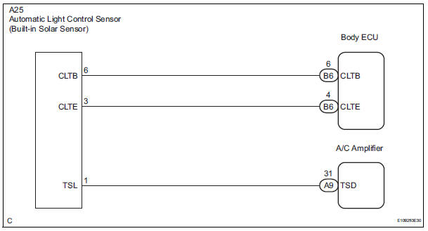
WIRING DIAGRAM
INSPECTION PROCEDURE
HINT:
- If DTC B1244 is output at the same time, troubleshoot DTC B1244 first (See page LI-16).
- If the check is performed in a dark place, DTC B1421/21 or B1424/24 (solar sensor circuit abnormal) may be output even though the system is normal.
1 READ VALUE OF INTELLIGENT TESTER
(a) Connect the intelligent tester to the DLC3.
(b) Turn the ignition switch to the ON position and turn the intelligent tester main switch on.
(c) Expose the sensing portion of the solar sensor to light.
HINT: Use an incandescent light for inspection.
(d) Select the item below in the DATA LIST, and read the display on the intelligent tester.
DATA LIST / AIR CONDITIONER: 
OK: The display is as specified in the normal condition column.
Result


2 CHECK HARNESS AND CONNECTOR (SOLAR SENSOR)

(a) Disconnect the solar sensor connector.
(b) Measure the voltage according to the value(s) in the table below.
Standard voltage


3 CHECK HARNESS AND CONNECTOR (SOLAR SENSOR - BODY ECU)

(a) Disconnect the body ECU connector.

(b) Measure the resistance according to the value(s) in the table below.
Standard resistance 


REPLACE BODY ECU
4 CHECK SOLAR SENSOR

(a) Remove the solar sensor with its connector still connected.
(b) Connect the positive (+) lead from the battery to terminal 6 (CLTB), and the negative (-) lead to terminal 3 (CLTE) of the solar sensor.
(c) Measure the voltage according to the value(s) in the table below.
Standard voltage 
NOTICE: While using the battery during inspection, do not bring the positive and negative tester probes too close to each other as a short circuit may occur.
HINT:
- Use an incandescent light for inspection. Bring it within about 30 cm (11.8 in.) of the solar sensor.
- As the inspection light is moved away from the sensor, the voltage increases.


5 CHECK HARNESS AND CONNECTOR (SOLAR SENSOR - A/C AMPLIFIER)

(a) Disconnect the solar sensor connector.

(b) Disconnect the A/C amplifier connector.
(c) Measure the resistance according to the value(s) in the table below.
Standard resistance 

REPLACE A/C AMPLIFIER
 Pressure Sensor Circuit
DTC B1423/23 Pressure Sensor Circuit
DESCRIPTION
This DTC is output when refrigerant pressure on the high pressure side is
extremely low (0.19 MPa (2.0
kgf/cm2, 28 psi) or less) or extremely high ...
 Air Mix Damper Position Sensor Circuit (Passenger Side)
DESCRIPTION
This sensor detects the position of the air mix control servo motor (air mix
damper) and sends the
appropriate signals to the A/C amplifier. The position sensor is built in the
a ...
Other materials:
Inspection
1. INSPECT PACK CLEARANCE OF FORWARD CLUTCH
(a) Install the forward clutch on the oil pump.
NOTICE:
Be careful not to damage the oil seal ring of oil
pump.
b) Using a dial indicator, measure the forward clutch
pack clearance while applying and releasing
compressed air (392 kPa, 4.0 kgf/cm ...
Rear wiper motor and bracket
COMPONENTS
REMOVAL
1. REMOVE REAR WIPER ARM
Remove the rear wiper arm head cap from the rear
wiper arm.
Remove the nut and the rear wiper arm.
2. REMOVE BACK DOOR GARNISH CENTER
3. REMOVE BACK DOOR SIDE GARNISH LH
4. REMOVE POWER BACK DOOR ROD
5. REMOVE BACK DOOR ...
Rear ceiling lights
Turns the lights on/off
When the personal/interior light
main switch is in the off position,
the rear ceiling lights will not turn
on even if the switch is on.
Adjusting the rear personal/interior lights angle (if equipped)
Push the edge of the light lens.
Illuminated entry system
...
