Toyota Sienna Service Manual: System Voltage

MONITOR DESCRIPTION
The battery supplies electricity to the ECM even when the ignition switch is off. This power allows the ECM to store data such as DTC history, freeze frame data and fuel trim values. If the battery voltage falls below a minimum level, these memories are cleared and the ECM determines that there is a malfunction in the power supply circuit. When the engine is next started, the ECM illuminates the MIL and sets the DTC.

HINT:
If DTC P0560 is set, the ECM does not store other DTCs.
MONITOR STRATEGY

TYPICAL ENABLING CONDITIONS

TYPICAL MALFUNCTION THRESHOLDS

WIRING DIAGRAM

INSPECTION PROCEDURE
HINT:
Read freeze frame data using the intelligent tester. The ECM records vehicle and driving condition information as freeze frame data the moment a DTC is stored. When troubleshooting, freeze frame data can be helpful in determining whether the vehicle was running or stopped, whether the engine was warmed up or not, whether the air-fuel ratio was lean or rich, as well as other data recorded at the time of a malfunction.
1 CHECK FUSE (EFI NO. 1 FUSE)
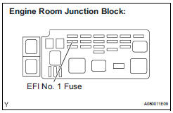
(a) Remove the EFI No. 1 fuse from the engine room junction block.
(b) Measure the resistance according to the value(s) in the table below.
Standard resistance: Below 1 Ω
(c) Reinstall the EFI No. 1 fuse.


2 INSPECT ECM (BATT VOLTAGE)
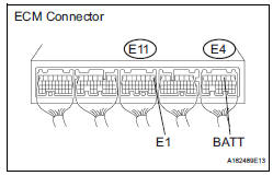
(a) Measure the voltage according to the value(s) in the table below.
Standard voltage 


REPLACE ECM (See page ES-498)
3 CHECK HARNESS AND CONNECTOR (ECM - EFI NO. 1 FUSE)

(a) Check the harness and the connector between the EFI No. 1 fuse and ECM.
(1) Remove the EFI No. 1 fuse from the engine room junction block.
(2) Disconnect the E4 ECM connector.
(3) Measure the resistance according to the value(s) in the table below.
Standard resistance : 
(4) Reconnect the ECM connector.
(5) Reinstall the EFI No. 1 fuse.


4 CHECK HARNESS AND CONNECTOR (EFI NO. 1 FUSE - BATTERY)

(a) Check the harness and the connector between the EFI No. 1 fuse and battery.
(1) Remove the EFI No. 1 fuse from the engine room junction block.
(2) Disconnect the negative battery cable.
(3) Measure the resistance according to the value(s) in the table below.
Standard resistance: 
(4) Reconnect the negative battery cable.
(5) Reinstall the EFI No. 1 fuse

5 INSPECT BATTERY
(a) Check that the battery is not depleted.


CHECK AND REPLACE ENGINE ROOM RELAY BLOCK
 Cold Start Ignition Timing Performance
DESCRIPTION
This monitor will run when the engine is started at -10 to 50°C (14 to 122°F)
of the engine coolant
temperature. The DTC will set after the engine idling for 13 seconds (2 trip
...
 Internal Control Module Random Access Memory (RAM) Error
DESCRIPTION
The ECM continuously monitors its own internal memory status, internal
circuits, and output signals
transmitted to the throttle actuator. This self-check ensures that the ECM is
...
Other materials:
Power Slide Door Pulse Sensor Malfunction on
Rear Left Door
DTC B2224 Power Slide Door Pulse Sensor Malfunction on
Rear Left Door
DESCRIPTION
A pulse sensor is built into slide door LH for jam and foreign
object detection and for slide door position
detection. The jam and foreign object detection feature of the pulse sensor
monitors the o ...
Installation
1. INSTALL FRONT SEAT ASSEMBLY RH
Place the seat assembly in the cabin.
NOTICE:
Be careful not to damage the body.
Connect the connectors under the seat assembly.
Tighten the 2 bolts on the front side of the seat
assembly.
Torque: 37 N*m (375 kgf*cm, 27 ft.*lbf)
...
Using the rear view monitor system
Screen description
The rear view monitor system screen will be displayed if the shift
lever is shifted to R while the engine switch is in the “ON” position
(vehicles without a smart key system) or IGNITION ON mode (vehicles
with a smart key system).
Vehicle width guide line
The lin ...
