Toyota Sienna Service Manual: Terminals of ECU
1. CHECK TRANSPONDER KEY AMPLIFIER

- Disconnect the I14 amplifier connector and measure the resistance between the terminal of the wire harness side connector and body ground.

If the result is not as specified, there may be a malfunction on the wire harness side.
- Reconnect the I14 amplifier connector and measure the resistance and voltage of each terminal of the connector

If the result is not as specified, the amplifier may have a malfunction.

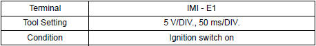
- Inspect using an oscilloscope.
- Waveform 1 (Reference):
- Waveform 2 (Reference):

2. CHECK TRANSPONDER KEY ECU ASSEMBLY
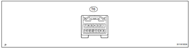
- Disconnect the T6 ECU connector and measure the resistance and voltage between each terminal of the wire harness side connector

If the result is not as specified, there may be a malfunction on the wire harness side.
- Reconnect the T9 ECU connector and measure the voltage of each terminal of the connector.

If the result is not as specified, the ECU may have a malfunction.

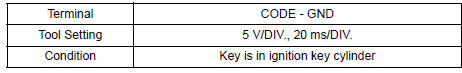
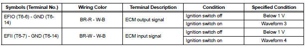
- Inspect using an oscilloscope.
- Wave form 1 (Reference):

- Wave form 2 (Reference):

- Wave form 3 (Reference):

- Wave form 4 (Reference):
3. CHECK ECM

- Disconnect the E11 ECM connector and measure the resistance between the terminal of the wire harness side connector and body ground.

If the result is not as specified, there may be a malfunction on the wire harness side.
- Reconnect the E11 ECM. Measure the voltage between each terminal of the connector according to the value(s) in the table below.

If the result is not as specified, there may be a malfunction on the wire harness side.

- Inspect using an oscilloscope.
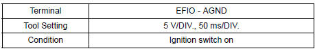
- Waveform 1 (Reference):
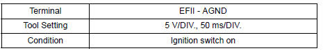
- Waveform 2 (Reference):

 Problem symptoms table
ENGINE IMMOBILISER SYSTEM
...
 Diagnosis system
1. CHECK DLC3
The vehicle's ECU uses ISO 15765-4 for
communication protocol. The terminal arrangement
of the DLC3 complies with SAE J1962 and matches
the ISO 15765-4 format.
...
Other materials:
Memory recall function
Each electronic key can be registered to recall your preferred driving
position.
Registering procedure
Record your driving position to button “1” or “2” before performing
the following:
Carry only the key you want to register, and then close the driver’s
door.
If 2 or more keys ar ...
Disassembly
1. INSPECT UNDERDRIVE PACK CLEARANCE
HINT:
(See page AX-262)
2. REMOVE UNDERDRIVE CLUTCH FLANGE NO.2 HOLE
SNAP RING
a) Using a screwdriver, remove the underdrive clutch
flange No.2 snap ring.
3. REMOVE UNDERDRIVE CLUTCH DISC NO.1
(a) Remove the flange, 4 discs and 4 plates from the
...
Short to GND in Side Squib RH Circuit
DTC B0112/41 Short to GND in Side Squib RH Circuit
DESCRIPTION
The side squib RH circuit consists of the center airbag sensor assembly and
the front seat side airbag
assembly RH.
The circuit instructs the SRS to deploy when deployment conditions are met.
DTC B0112/41 is recorded when a sh ...
