Toyota Sienna Service Manual: Terminals of ECU
1. CHECK DRIVER SIDE J/B ASSEMBLY (MULTIPLEX NETWORK BODY ECU)
- Disconnect the 1C, 1J, 1L, 1K, 1P, B6, B7 and B9 J/ B connectors.

- Measure the voltage and resistance according to the value(s) in the table below.
Standard
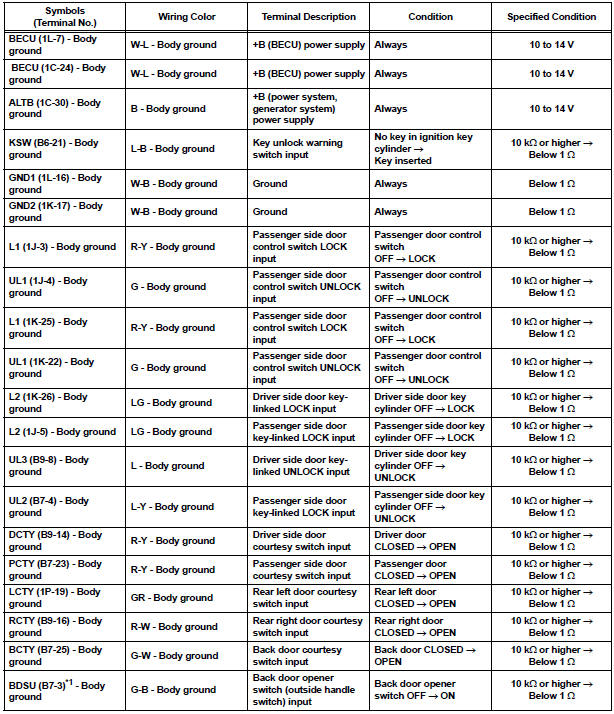
HINT:
- If the result is not as specified, there may be a malfunction on the wire harness side.
- *1: w/o Power back door
- Reconnect the J/B and ECU connectors and measure the voltage according to the value(s) in the table below.
Standard voltage


HINT:
- *1: w/o Power Back Door
- Use an oscilloscope to check the output voltages of terminals LSWD, LSWP, LSWL and LSWR.
- If the result is not as specified, the J/B (body ECU) may have a malfunction.
2. CHECK POWER BACK DOOR ECU (w/ Power back door system)
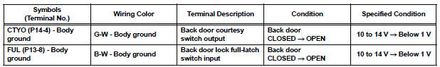
- Disconnect the P13 and P14 ECU connectors.

- Measure the voltage and resistance according to the value(s) in the table below.
Standard

HINT: If the result is not as specified, there may be a malfunction on the wire harness side.
- Reconnect the ECU connectors and measure the voltage according to the value(s) in the table below.
Standard voltage
HINT: If the result is not as specified, the ECU may have a malfunction.
 Problem symptoms table
HINT:
Inspect the fuse and relay before investigating the suspected
areas shown in the table below.
POWER DOOR LOCK CONTROL SYSTEM
...
 Diagnosis system
1. CHECK DLC3
The vehicle's ECU uses ISO 15765-4 for
communication protocol. The terminal arrangement
of the DLC3 complies with SAE J1962 and matches
the ISO 15765-4 format.
...
Other materials:
Operation check
1. NOTICE WHEN CHECKING THE FOLLOWING
Power door lock/unlock function:
The wireless door lock control function operates
only when the following 3 conditions are met:
No key is inserted in the ignition key cylinder.
All the doors are closed.
The power door lock sys ...
System description
1. GENERAL
In conjunction with impact absorbing structure for a
frontal collision, the SRS (Supplemental Restraint
System) driver airbag and front passenger airbag
were designed to supplement seat belts in the event
of a frontal collision in order to help reduce shock to
the head and c ...
Installation
1. INSTALL VENTILATION VALVE
(a) Install the ventilation valve.
(1) Apply adhesive to 2 or 3 threads.
Adhesive:
Part No. 08833-00070, Three Bond 1324 or
equivalent
(2) Install the ventilation valve.
Torque: 27 N*m (275 kgf*cm, 20 ft.*lbf)
2. CONNECT VENTILATION HOSE
(a) Connect ...
