Toyota Sienna Service Manual: Transmission Range Sensor Circuit Malfunction (PRNDL Input)
 DESCRIPTION
The park/neutral position switch detects the shift lever position and sends signals to the ECM.
MONITOR DESCRIPTION
These DTCs indicate a problem with the park/neutral position switch and the wire harness in the park/ neutral position switch circuit.
The park/neutral position switch detects the shift lever position and sends a signal to the ECM.
For security, the park/neutral position switch detects the shift lever position so that engine can be started only when the shift lever is in the P or N position The park/neutral position switch sends a signal to the ECM according to the shift position (P, R, N or D).
The ECM determines that there is a problem with the switch or related parts if in receives more than 1 position signal simultaneously. The ECM will turn on the MIL and store the DTC.
MONITOR STRATEGY

TYPICAL ENABLING CONDITIONS

TYPICAL MALFUNCTION THRESHOLDS
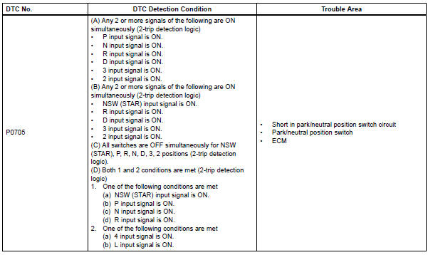
1. One of the following conditions are met: Condition (A), (B), (C) and (D)

COMPONENT OPERATING RANGE
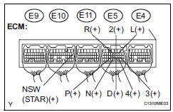
WIRING DIAGRAM

1 INSPECT PARK/NEUTRAL POSITION SWITCH ASSEMBLY

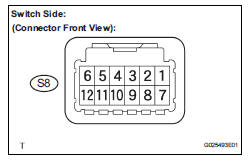
(a) Disconnect the park/neutral position switch connector.
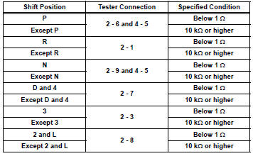
(b) Measure resistance according to the value(s) in the table below when the shift lever is moved to each position.
Standard resistance

2 INSPECT SHIFT LOCK CONTROL UNIT ASSEMBLY
(a) Connect the park/neutral position switch connector.
(b) Disconnect the transmission control switch connector of shift lock control unit assembly.
(c) Measure resistance according to the value(s) in the table below when the shift lever is moved to each position.
Standard resistance


3 CHECK HARNESS AND CONNECTOR (PARK/NEUTRAL POSITION SWITCH - ECM)
(a) Connect the transmission control switch connector of shift lock control unit assembly.
(b) Turn the ignition switch to the ON position, and measure the voltage according to the value(s) in the table below when the shift lever is moved to each position.
Standard voltage

HINT: *: The voltage will drop slightly due to lighting up of the back up light.


REPLACE ECM
 Diagnostic trouble code chart
If a DTC is displayed during the DTC check, check the parts
listed in the table below and proceed to the page given.
HINT:
*1: Comes on MIL (Malfunction Indicator Lamp) light up
*2: "DT ...
 Transmission Fluid Temperature Sensor "A"
DESCRIPTION
The ATF (Automatic Transmission Fluid) temperature sensor converts the fluid
temperature into a
resistance value which is input into the ECM.
The ECM applies a voltage to the te ...
Other materials:
Power back door warning buzzer
INSPECTION
1. POWER BACK DOOR WARNING BUZZER
Check the resistance of the buzzer.
Resistance
If the result is not as specified, replace the buzzer.
NOTICE:
The circuit that causes the buzzer to sounds
is built into the back door ECU, not around
the buzzer.
Directly applying ...
How to proceed with
troubleshooting
HINT:
Troubleshoot in accordance with the procedures on the
following pages.
1 VEHICLE BROUGHT TO WORKSHOP
2 DTC CHECK
Check for DTCs and make a note of the code that is
output (See page MP-14).
Delete the DTC.
Check if the DTC is output once again when the problem
symptom is simulat ...
Installation
1. INSTALL ACCELERATOR PEDAL ROD
NOTICE:
Avoid physical shock to the accelerator pedal
assembly.
Do not disassemble the accelerator pedal
assembly.
Install the accelerator pedal rod with the 2 nuts.
Torque: 4.9 N*m (50 kgf*cm, 43 in.*lbf)
Connect the ...
