Toyota Sienna Service Manual: Vehicle Speed Signal Circuit between Radio and Navigation Assembly and Combination Meter
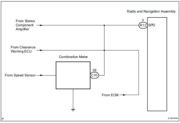
DESCRIPTION The radio and navigation assembly receives a vehicle speed signal from the combination meter and information about the GPS antenna, and then adjusts vehicle position.
HINT:
- A voltage of 12 V or 5 V is output from each ECU and then input to the combination meter. The signal is changed to a pulse signal at the transistor in the combination meter. Each ECU controls the respective system based on the pulse signal.
- If a short occurs in an ECU, all systems in the diagram below will not operate normally.
WIRING DIAGRAM
INSPECTION PROCEDURE
1 CHECK OPERATION OF SPEEDOMETER
- Drive the vehicle and check if the function of the speedometer on the combination meter is normal.
OK: Actual vehicle speed and the speed indicated on the speedometer are the same
HINT: The vehicle speed sensor is functioning normally when the indication on the speedometer is normal.
2 INSPECT RADIO AND NAVIGATION ASSEMBLY
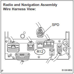
- Disconnect the radio and navigation assembly connector R12.
- Measure the voltage.
- Jack up either one of the drive wheels.
- Move the shift lever to the neutral position.
- Turn the ignition switch to the ON position
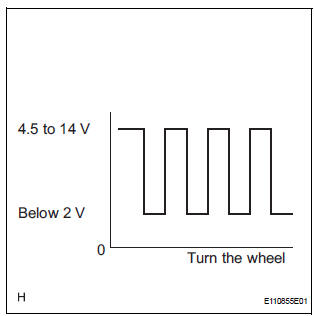
- Measure the voltage between terminal SPD of the radio and navigation assembly and body ground when the drive wheels are turned slowly.
OK: Voltage pulses as shown in the illustration.
3 CHECK HARNESS AND CONNECTOR (COMBINATION METER - RADIO AND NAVIGATION ASSEMBLY)
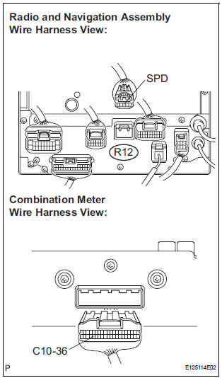
- Disconnect the radio and navigation assembly connector R12 and combination meter connector C10.
- Measure the resistance according to the value(s) in the table below.
Standard resistance
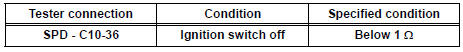
4 CHECK HARNESS AND CONNECTOR (COMBINATION METER - RADIO AND NAVIGATION ASSEMBLY)
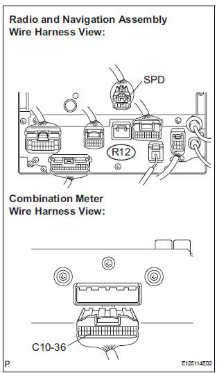
- Disconnect the radio and navigation assembly connector R12 and combination meter connector C10.
- Measure the resistance according to the value(s) in the table below.
Standard resistance

HINT: If the resistance between terminal SPD and body ground is less than 10 kΩ, there may be a short in a wire harness, connector, or an ECU.
REPLACE COMBINATION METER
 Black Screen
INSPECTION PROCEDURE
1 CHECK DISPLAY SETTING
Check that the display is not in "Screen OFF" mode.
OK:
The display setting is not in "Screen OFF" mode.
2 CHECK IMAGE QUALIT ...
 Steering Pad Switch Circuit
DESCRIPTION
This circuit sends an operation signal from the steering pad switch to the
radio receiver.
If there is an open in the circuit, the navigation system cannot be operated
using the st ...
Other materials:
Making a call
Once a Bluetooth® phone is registered, you can make a call
using the following procedure:
Dialing
Display the phone screen.
Select the “Dial Pad” tab and enter a phone number.
To delete the input phone number, select
.
For the first digit, you can enter “+” by selecting “&# ...
Oxygen Sensor Heater Control Circuit Low/ Oxygen Sensor Heater Control
Circuit High/ Oxygen Sensor Heater Circuit Malfunction
DTC P0037 Oxygen Sensor Heater Control Circuit Low
(Bank 1 Sensor 2)
DTC P0038 Oxygen Sensor Heater Control Circuit High
(Bank 1 Sensor 2)
DTC P0057 Oxygen Sensor Heater Control Circuit Low
(Bank 2 Sensor 2)
DTC P0058 Oxygen Sensor Heater Control Circuit High
(Bank 2 Sensor 2)
DTC P0141 Oxyg ...
Vehicle Speed Sensor "A"
DESCRIPTION
The speed sensor detects the wheel speed and sends the appropriate signals to
the skid control ECU.
The skid control ECU converts these wheel speed signals into a 4-pulse signal
and outputs it to the ECM
via the combination meter. The ECM determines the vehicle speed based o ...
