Toyota Sienna Service Manual: ACIS Control Circuit
DESCRIPTION
This circuit opens and closes the Intake Air Control Valve (IACV) in response to changes in the engine load in order to increase the intake efficiency (ACIS: Acoustic Control Induction System).
When the engine speed is between 0 and 4450 rpm and the throttle valve opening angle is 60 or more, the ECM supplies current to the VSV (ON status), to close the IACV. Under other conditions, the VSV is usually OFF and the IACV is open.

WIRING DIAGRAM

INSPECTION PROCEDURE
1 PERFORM ACTIVE TEST BY INTELLIGENT TESTER (OPERATE VSV FOR ACIS)
- Connect the intelligent tester to the DLC3.
- Start the engine and turn the intelligent tester on.
- Select the following menu items: DIAGNOSIS / ENHANCED OBD II / ACTIVE TEST / INTAKE CTL VSV1. Operate the VSV for AICS.
OK: Operational noise can be heard.
2 CHECK INTAKE AIR CONTROL VALVE (OPERATION)

- Disconnect the V14 VSV for ACIS connector.
- Apply battery voltage between the terminals of the air intake valve connector.
- Check the air intake valve operation.
OK: Operational noise can be heard.
- Reconnect the VSV for ACIS connector.
3 CHECK HARNESS AND CONNECTOR (VSV FOR ACIS - ECM)

- Check the wire harness and connectors between the VSV for ACIS and ECM.
- Disconnect the V14 VSV for ACIS connector.
- Disconnect the E9 ECM connector.
- Measure the resistance according to the value(s) in the table below.
Standard resistance : Check for open

Check for short

- Reconnect the VSV for ACIS connector.
- Reconnect the ECM connector
4 INSPECT FUSE (EFI NO. 2 FUSE)

- Check the EFI No. 2 fuse.
- Remove the EFI No. 2 fuse from the engine room junction block.
- Measure the EFI No. 2 fuse resistance.
Standard resistance: Below 1 Ω
- Reinstall the EFI No. 2 fuse.
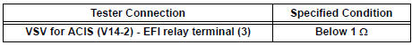
5 CHECK HARNESS AND CONNECTOR (VSV FOR ACIS - EFI RELAY)

- Check the wire harness between the VSV for ACIS connector and EFI relay.
- Remove the EFI relay from the engine room junction block.
- Disconnect the V14 VSV connector.
- Measure the resistance according to the value(s) in the table below.
Standard resistance : Check for open
- Reinstall the EFI relay.
- Reconnect the VSV connector.
CHECK ECM POWER SOURCE CIRCUIT
 Cranking Holding Function Circuit
DESCRIPTION
The system detects the ignition switch's starting signal (STSW) and then
supplies current to the starter
until the ECM judges that the engine has started successfully. The purpose is t ...
 Air Intake Control Circuit
DESCRIPTION
The air cleaner is equipped with two inlets, one of which is opened or closed
by the Air Intake Control
Valve (AICV). This system reduces intake noise and increases engine power at
l ...
Other materials:
Throttle / Pedal Position Sensor / Switch "A"
HINT:
These DTCs relate to the Throttle Position (TP) sensor.
DESCRIPTION
HINT:
This ETC (Electrical Throttle Control System) does not use a throttle cable.
The Throttle Position (TP) sensor is mounted on the throttle body, and detects
the opening angle of the
throttle valve. This sens ...
Initialization
Items to initialize
The following items must be initialized for normal system operation
after such cases as the battery being reconnected, or maintenance
being performed on the vehicle.
Item
When to initialize
Power sliding door
(if equipped)
After reconnecting o ...
Slide door lock release motor
Inspection
1. INSPECT SLIDE DOOR LOCK RELEASE MOTOR ASSEMBLY LH
Apply battery voltage and inspect operation of the
motor.
OK
If the result is not as specified, replace the motor
assembly.
2. INSPECT SLIDE DOOR LOCK RELEASE MOTOR ASSEMBLY RH
Apply battery voltage and insp ...