Toyota Sienna Service Manual: Active Control Engine Mount System
DESCRIPTION
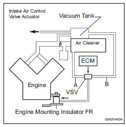
LOCATION

The Active Control Engine Mount (ACM) system decreases engine vibration at engine idling using the ACM VSV. The VSV is controlled by a pulse signal transmitted to the VSV from the ECM. The frequency of this pulse signal is matched to the engine speed to decrease engine vibration.
WIRING DIAGRAM

INSPECTION PROCEDURE
1 CHECK VACUUM HOSES
(a) If the hose is damaged, replace the vacuum hose assembly.
(b) Check the air and vacuum hoses for looseness, disconnection and blockage.


2 CHECK VACUUM

(a) Start the engine.
(b) Disconnect the vacuum hose from the air cleaner cap.
(c) Check that the disconnected port located on the vacuum tank applies suction to your finger.
OK: Vacuum pressure exists.
(d) Reconnect the vacuum hose.


3 INSPECT ECM
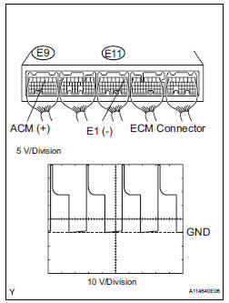
(a) Connect the oscilloscope between terminals ACM and E1 of the E9 and E11 ECM connectors.
(b) Warm up the engine to normal operating temperature.
(c) Turn the A/C switch on.
(d) Measure the voltage according to the value(s) in the table below.
Standard voltage 


4 INSPECT DUTY VACUUM SWITCHING VALVE (RESISTANCE)

(a) Disconnect the V3 VSV for ACM connector.
(b) Measure the resistance according to the value(s) in the table below.
Standard resistance: 19 to 21 Ω at 20°C (68°F)
(c) Reconnect the VSV for ACM connector.


5 CHECK HARNESS AND CONNECTOR (VSV FOR ACM - ECM)

(a) Check the wire harness between the VSV for ACM connector and the ECM connector.
(1) Disconnect the V3 VSV for ACM connector.
(2) Disconnect the E9 ECM connector.
(3) Measure the resistance according to the value(s) in the table below.
Standard resistance: 
(4) Reconnect the ECM connector.


6 INSPECT FUSE (EFI NO. 2 FUSE)

(a) Remove the EFI No. 2 fuse from the engine room junction block.
(b) Measure the resistance according to the value(s) in the table below.
Standard resistance: Below 1 Ω
(c) Reinstall the EFI No. 2 fuse.


7 INSPECT RELAY (EFI RELAY)

(a) Remove the EFI relay from the engine room junction block.
(b) Measure the resistance according to the value(s) in the table below.
Standard resistance 
(c) Reinstall the EFI relay.


8 CHECK HARNESS AND CONNECTOR (VSV FOR ACM - EFI RELAY)

(a) Check the wire harness between the VSV for ACM and the EFI relay.
(1) Remove the EFI relay from the engine room junction block.
(2) Measure the resistance according to the value(s) in the table below.
Standard resistance: 
(3) Reconnect the VSV for ACM connector.
(4) Reinstall the EFI relay.


CHECK ECM POWER SOURCE CIRCUIT
9 INSPECT DUTY VACUUM SWITCHING VALVE (OPERATION)

(a) Remove the VSV for ACM.
(b) Check operation of the VSV for ACM when positive battery voltage is applied to the terminals of the VSV for ACM connector.
Positive battery voltage is not applied: The air from pipe G is flowing out through pipes E and H.
Positive battery voltage is applied: The air from pipe F is flowing out through pipes E and H.
(c) Reinstall the VSV for ACM.


10 INSPECT ENGINE MOUNTING INSULATOR ASSEMBLY FRONT

(a) Disconnect the vacuum hose from the front engine mount insulator.
(b) Using a vacuum pump, apply vacuum of 80 kPa (600 mmHg, 25 in.Hg) and wait for 1 minute.
(c) Check that there is no change in the needle movement of the vacuum pump gauge.
(d) Check that there is no fluid leakage caused by a break in the diaphragm.
OK: Vacuum pressure exists.
(e) Reconnect the vacuum hose.


SYSTEM OK
 A/F Sensor Circuit Slow Response
HINT:
DTC P2A00 indicates malfunctions related to the bank 1 A/F sensor.
DTC P2A03 indicates malfunctions related to the bank 2 A/F sensor.
Bank 1 refers to the bank that includes cylinder ...
 EVAP System
RELATED DTCS
If any EVAP system DTCs are set, the malfunctioning area can be determined
using the table below.
NOTICE:
If the 0.02 inch reference pressure difference between the ...
Other materials:
Auto Up Operation does not Fully Close Power Window (Jam
Protection Function is Activated)
DESCRIPTION
If AUTO UP operation does not fully close the power window, the following
conditions may be the cause.
The reset of the power window motor has not been completed,
resulting in activation of the jam
protection function.
The memory of the power window switch misse ...
DVD Error/ Excess Current/ Tray Insertion / Ejection Error
DTC 44-44 DVD Error
DTC 44-48 Excess Current
DTC 44-50 Tray Insertion / Ejection Error
DESCRIPTION
DTC No.
DTC Detecting Condition
Trouble Area
44-44
Operation error in the DVD mechanism.
Television display assembly
44-48
Excess current is ...
Knock Sensor Circuit Low Input/ Knock Sensor Circuit High Input
DTC P0327 Knock Sensor 1 Circuit Low Input (Bank 1 or
Single Sensor)
DTC P0328 Knock Sensor 1 Circuit High Input (Bank 1 or
Single Sensor)
DTC P0332 Knock Sensor 2 Circuit Low Input (Bank 2)
DTC P0333 Knock Sensor 2 Circuit High Input (Bank 2)
DESCRIPTION
A flat type knock sensor (non-resona ...