Toyota Sienna Service Manual: Adjustment
CAUTION:
- Do not stare at the luminous portion of the laser during adjustment. The intensity of the laser light is low, but it may result in loss of sight.
- If operation is not carried out as specified, there may be a risk that you are exposed to hazardous radiation.
HINT:
- After replacing the ECM on vehicles with a dynamic laser cruise control system, it is necessary to initialize the ECM so that the ECM can recognize the dynamic laser cruise control system.
- After replacing the distance control ECU, it is necessary to initialize the distance control ECU so that the ECU can recognize the specification of the vehicle.
- There is a limitation on laser beam axis adjustment.
- Since the laser sensor is installed in the bumper reinforcement, it is important that the laser sensor, bumper reinforcement, etc. are installed properly.
- When the sensor is removed from the vehicle for trouble diagnosis or repair, it is necessary to adjust the laser beam axis after the operation.
1. ADJUST LASER SENSOR
NOTICE:
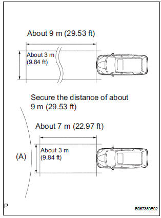
- Perform measurement indoors on a level ground and in front of a blank wall. Park the vehicle at least 9 m (29.53 ft) from the wall. When performing adjustment outdoors, make sure that it is not raining or snowing.
- Check that there are no reflective materials in the surroundings or on the ground.
- If you can not secure a distance of about 9 m (29.53 ft) in front of the vehicle, be sure to secure at least 7 m (22.97 ft) from the vehicle, and cover the area marked [A] with a black cloth. If not covered with a black cloth, the laser sensor may detect something other than the target and it will fail to adjust properly.
- Preparation for adjusting the laser beam axis
- Adjust the tires pressure properly.
- Luggage in the vehicle such as in the trunk should be unloaded.
- Clean the light-luminous and light-receiving portions of the laser sensor.
- Prepare a 10 m (32.81 ft) string, a string with a sharp-pointed weight, and a 5 m (16.41 ft) tape measure.
- Reflector (SST) placement
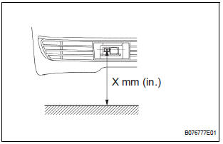
- Measure the height to the center of the laser luminous portion.
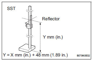
- Adjust the center height of the reflector 48 mm
(1.89 in.) higher than the center of the luminous
portion.
SST 09870-60000 (09870-60010, 09870- 60020)
NOTICE: Adjust it as precise as possible.
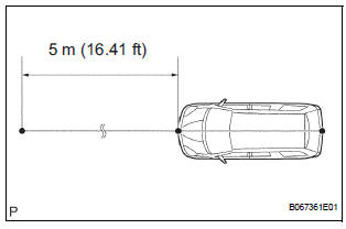
- From the center (center of the emblem) of the front and rear bumpers, hang down the sharppointed weight and mark the center points (both front and rear) of the vehicle on the ground.
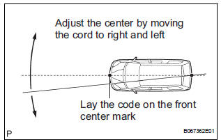
- Fix one end of the string to the rear center mark
and move the other end to the right and left at a
point 5 m (16.41 ft) from the front of the vehicle.
Make a 5 m (16.41 ft) mark when the string and the front vehicle center mark intersect.
- From the 5 m (16.41 ft) marked position, measure 569 mm (22.4 in.) to the right and place the reflector there.
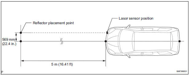
NOTICE: Perform it as precise as possible.
- Adjust the laser beam axis (procedure [B])
- Turn the ignition switch to ON.
- Push the cruise control main switch button on.
- Connect the intelligent tester to the DLC3, and turn the power ON.
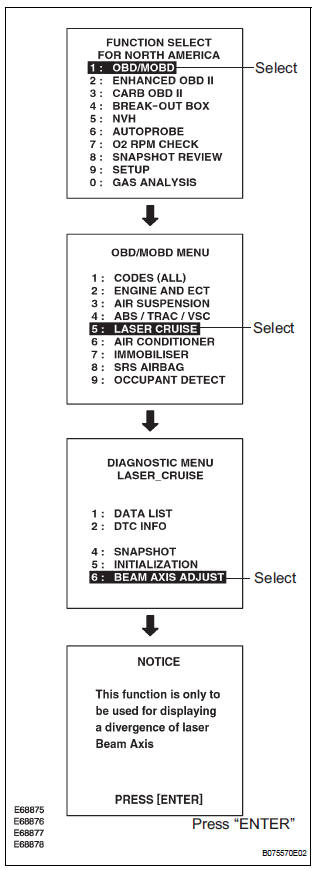
- Operate by following the screen menu and select "BEAM AXIS ADJUST" of the Laser Cruise Control, then press "ENTER".
HINT:
- Pressing "ENTER" will make the ECM transfer to BEAM AXIS ADJUSTMENT MODE.
- When the ECM transfers to BEAM AXIS ADJUSTMENT MODE, the buzzer sounds for 1 second.
- Confirm the current value of the laser beam (The default reading is 6.3 when the reflector is out of range).
- Move the reflector either to right or left by 100
mm (19.69 in.) and check that the value
changes.
NOTICE: When the values do not change, it is possible that the direction of the laser radar sensor is greatly off target, and that the laser radar sensor is aiming at something different. Check the installation condition of the laser radar sensor.
- Return the reflector to the original position and read the current angle.
Standard

HINT: If the vehicle dimensions are correct, the values should be within the above standard value range. If any value is out of the range, check the installation condition of the bumper reinforcement, etc. as it can not be adjusted automatically.
- Turn the headlight dimmer switch to the TAIL position.
- Beam axis adjustment will be performed automatically.
- When the adjustment is completed, the UPPER/ LOWER SIDE and RIGHT/LEFT SIDE indicators show 0 and the system beeps for 10 seconds. During this time, UPPER and LOWER flash alternately on the screen, and LEFT and RIGHT flash alternately on the screen.
NOTICE: Adjustment values are calculated and then stored in the laser sensor. As the system is not controlled mechanically, the same value as before is displayed to adjust the beam axis.
INSTALLATION
1. INSTALL LASER SENSOR
NOTICE: Do not install the laser sensor if it has been damaged or received some sort of shock.
2. INSTALL FRONT BUMPER REINFORCEMENT SUBASSEMBLY
 Removal
1. REMOVE FRONT FENDER LINER LH
2. REMOVE FRONT FENDER LINER RH
3. REMOVE FRONT BUMPER COVER
4. REMOVE FRONT BUMPER ENERGY ABSORBER
5. REMOVE FRONT BUMPER REINFORCEMENT SUBASSEMBLY
6. REMOVE LASE ...
 Lighting
...
Other materials:
ECM / PCM Processor
DTC P0606 ECM / PCM Processor
DESCRIPTION
The ECM continuously monitors its internal processors (CPUs), A/F sensor
transistors and heated oxygen
sensor (HO2S) transistors. This self-check ensures that the ECM is functioning
properly. These are
diagnosed by internal "mirroring" of t ...
Removal
1. DISCONNECT CABLE FROM NEGATIVE BATTERY
TERMINAL
CAUTION:
Wait for 90 seconds after disconnecting the cable to
prevent the airbag working.
2. REMOVE FRONT SEAT ASSEMBLY
HINT:
Refer to the instructions for removal of the front seat
assembly (for flat type).
Refer to the in ...
Monitor result information
If you use a generic scan tool, multiply the test value by
the scaling value listed below.
...