Toyota Sienna Service Manual: Brake Switch "A" Circuit
DTC P0571 Brake Switch "A" Circuit
DESCRIPTION
When the brake pedal is depressed, the stop light switch sends a signal to the ECM. When the ECM receives this signal, it cancels the cruise control. The fail-safe function operates to enable normal driving even if there is a malfunction in the stop light signal circuit. The cancellation condition occurs when voltage is applied to terminal STP. When the brake is applied, voltage is normally applied to terminal STP of the ECM through the STOP fuse and the stop light switch, and the ECM turns the cruise control off.
|
DTC No. |
DTC Detection Condition |
Trouble Area |
|
P0571 |
Voltage of STP terminal and that of ST1- terminal of ECM are less than 1 V for 0.5 sec. or more. |
|
WIRING DIAGRAM

INSPECTION PROCEDURE
1 READ VALUE OF INTELLIGENT TESTER
- Connect the intelligent tester to the DLC3.
- Turn the ignition switch to the ON position, and turn the intelligent tester main switch on.
- Check the DATA LIST for proper functioning of the stop light switch.
ECM (Cruise control):

OK: When the brake pedal is operated, the display changes as shown above.
REPLACE ECM
2 CHECK HARNESS AND CONNECTOR (STOP LIGHT SWITCH - BATTERY)

- Disconnect the S12 connector from the stop light switch.
- Measure the voltage according to the value(s) in the table below.
Standard voltage

3 INSPECT STOP LIGHT SWITCH
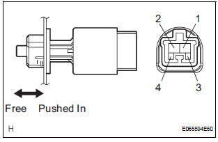
- Remove the stop light switch.
- Measure the resistance according to the value(s) in the table below.
Standard resistance

- Install the stop light switch.
4 CHECK ECM

- Reconnect the S12 stop light switch connector.
- Disconnect the E4 connector from the ECM.
- Turn the ignition switch to the ON position.
- Measure the voltage according to the value(s) in the table below.
Standard voltage

REPLACE ECM
 Vehicle Speed Sensor Malfunction
DTC P0500 Vehicle Speed Sensor Malfunction
DTC P0503 Vehicle Speed Sensor Circuit Malfunction
DESCRIPTION
The cruise control system uses the same vehicle speed signal that is sent to
the ECM for ...
 Input Signal Circuit Malfunction
DTC P0607 Input Signal Circuit Malfunction
DESCRIPTION
This DTC indicates internal abnormalities of the ECM.
DTC No.
Detection Item
Trouble Area
P0607
The E ...
Other materials:
Short to GND in Front Pretensioner Squib RH
Circuit
DTC B0132/61 Short to GND in Front Pretensioner Squib RH
Circuit
DESCRIPTION
The front pretensioner squib RH circuit consists of the center airbag sensor
assembly and the front seat
outer belt assembly RH.
This circuit instructs the SRS to deploy when deployment conditions are met.
DTC B ...
Types of child restraints
Child restraint systems are classified into the following 3 types
according to the age and size of the child:
Rear facing - Infant seat/convertible seat
Forward facing - Convertible seat
Booster seat
Selecting an appropriate child restraint system
Use a child rest ...
Installation
1. INSTALL FRONT SUSPENSION ARM SUBASSEMBLY LOWER NO.1 LH
(a) Install the front lower arm bush stopper to the front
suspension arm sub-assembly lower No.1 LH.
(b) Install the bolt and nut to the rear side of the front
suspension arm sub-assembly lower No.1 LH.
Torque: 206 N*m (2,100 kgf ...