Toyota Sienna Service Manual: Camshaft Position "B" Actuator Circuit

DESCRIPTION
The Variable Valve Timing (VVT) system includes the ECM, OCV and VVT controller. The ECM sends a target duty-cycle control signal to the OCV. This control signal regulates the oil pressure supplied to the VVT controller. Camshaft timing control is performed according to engine operating conditions such as the intake air volume, throttle valve position and engine coolant temperature. The ECM controls the OCV, based on the signals transmitted by several sensors. The VVT controller regulates the exhaust camshaft angle using oil pressure through the OCV. As a result, the relative positions of the camshaft and crankshaft are optimized, the engine torque and fuel economy improve, and the exhaust emissions decrease under overall driving conditions. The ECM detects the actual exhaust valve timing using signals from the camshaft and crankshaft position sensors, and performs feedback control. This is how the target intake valve timing is verified by the ECM.


MONITOR DESCRIPTION
The ECM optimizes the valve timing using the VVT system to control the exhaust camshaft. The VVT system includes the ECM, the OCV and the VVT controller. The ECM sends a target duty-cycle control signal to the OCV. This control signal regulates the oil pressure supplied to the VVT controller. The VVT controller can advance or retard the exhaust camshaft.
After the ECM sends the target duty-cycle signal to the OCV, the ECM monitors the OCV current to establish an actual duty-cycle. The ECM determines the existence of a malfunction and sets the DTC when the actual duty-cycle ratio varies from the target duty-cycle ratio.
MONITOR STRATEGY

TYPICAL ENABLING CONDITIONS

TYPICAL MALFUNCTION THRESHOLDS

COMPONENT OPERATING RANGE

WIRING DIAGRAM

INSPECTION PROCEDURE
HINT:
- If DTC P0013 is displayed, check the exhaust camshaft circuit for the bank 1 VVT system.
- Bank 1 refers to the bank that includes cylinder No. 1.
- If DTC P0023 is displayed, check the exhaust camshaft circuit for the bank 2 VVT system.
- Bank 2 refers to the bank that does not include cylinder No. 1.
- Read freeze frame data using an intelligent tester. The ECM records vehicle and driving condition information as freeze frame data the moment a DTC is stored. When troubleshooting, freeze frame data can be helpful in determining whether the vehicle was running or stopped, whether the engine was warmed up or not, whether the air-fuel ratio was lean or rich, as well as other data recorded at the time of a malfunction.
1 PERFORM ACTIVE TEST BY INTELLIGENT TESTER (OPERATE OCV)
(a) Connect the intelligent tester to the DLC3.
(b) Start the engine and turn the tester on.
(c) Warm up the engine.
(d) Enter the following menus: DIAGNOSIS / ENHANCED OBD II / ACTIVE TEST / VVT CTRL B1 or VVT CTRL B2.
(e) Check the engine speed while operating the Oil Control Valve (OCV) using the tester.
OK


CHECK FOR INTERMITTENT PROBLEMS
2 INSPECT CAMSHAFT TIMING OIL CONTROL VALVE ASSEMBLY

(a) Disconnect the C26 or C25 camshaft timing oil control valve (OCV) connector.
(b) Measure the resistance according to the value(s) in the table below.
Standard resistance 
(c) Reconnect the OCV connector.


REPLACE CAMSHAFT TIMING OIL CONTROL VALVE ASSEMBLY (See page ES-486)
3 CHECK HARNESS AND CONNECTOR (OCV - ECM)

(a) Disconnect the C25 or C26 camshaft timing oil control valve (OCV) connector.
(b) Disconnect the E11 ECM connector.
(c) Measure the resistance according to the value(s) in the table below.
Standard resistance (Check for open)

Standard resistance (Check for short)
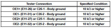
(d) Reconnect the ECM connector.
(e) Reconnect the OCV connector.


REPLACE ECM (See page ES-498)
 Camshaft Position "A" - Timing Over
HINT:
If DTC P0011, P0012, P0021 or P0022 is present, check the VVT (Variable Valve
Timing) system.
DESCRIPTION
Refer to DTC P0010 (See page ES-75).
DTC No.
DTC Detection Condition ...
 Camshaft Position "B" - Timing Over
HINT:
If DTC P0014, P0015, P0024 or P0025 is present, check the VVT (Variable Valve
Timing) system.
DESCRIPTION
Refer to DTC P0013 (See page ES-87).
MONITOR DESCRIPTION
DTC P0014 and P0 ...
Other materials:
Scratched / Reversed Disc
DTC 62-46 Scratched / Reversed Disc
DTC 63-46 Scratched / Reversed Disc
DESCRIPTION
DTC No.
DTC Detecting Condition
Trouble Area
62-46
Scratches or dirt is found on CD surface or CD is set
upside down.
CD
Radio receiver
...
Location of the spare tire, jack and tools
Spare tire
Jack handle
Tire bag
Jack
Wheel nut wrench
Adapter socket
Tire strap
WARNINGUsing the tire jack
Observe the following precautions.
Improper use of the tire jack may cause the vehicle to suddenly fall off
the jack, leading to death or serious injury. ...
Installation
1. INSTALL SIDE REAR WINDOW WEATHERSTRIP LH
2. INSTALL QUARTER WINDOW LOCK ASSEMBLY LH
3. INSTALL POWER VENT WINDOW MOTOR
ASSEMBLY LH
4. INSTALL SIDE WINDOW ASSEMBLY REAR LH
5. INSTALL RR WINDOW SIDE GARNISH ASSEMBLY
LH
6. INSTALL RR WINDOW SIDE GARNISH ASSEMBLY
NO.2 LH
7. REMOVE QUARTER TR ...