Toyota Sienna Service Manual: Center Airbag Sensor Assembly Communication Circuit Malfunction
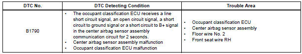
DTC B1790 Center Airbag Sensor Assembly Communication Circuit Malfunction
DESCRIPTION
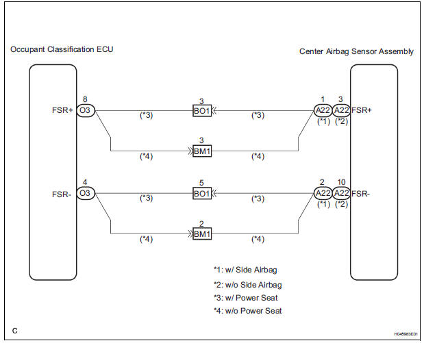
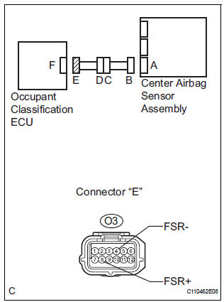
The center airbag sensor assembly communication circuit consists of the occupant classification ECU and the center airbag sensor assembly.
DTC B1790 is recorded when a malfunction is detected in the center airbag sensor assembly communication circuit.
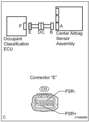
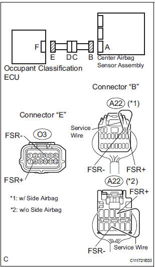
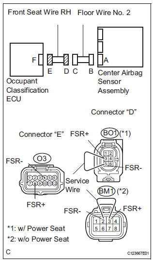
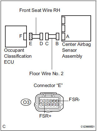
WIRING DIAGRAM
INSPECTION PROCEDURE
HINT:
- If troubleshooting (wire harness inspection) is difficult to perform, remove the front passenger seat installation bolts to see the under surface of the seat cushion.
- In the above case, hold the seat so that it does not fall down. Holding the seat for a long period of time may cause a problem, such as seat rail deformation. Hold the seat only as necessary.
1 CHECK DTC
- Turn the ignition switch to the ON position.
- Clear the DTCs stored in the memory.
HINT: First clear DTCs stored in the occupant classification ECU and then in the center airbag sensor assembly.
- Turn the ignition switch to the LOCK position.
- Turn the ignition switch to the ON position.
- Check the DTCs.
OK: DTC B1790 is not output.
HINT: Codes other than DTC B1790 may be output at this time, but they are not related to this check.
2 CHECK CONNECTION OF CONNECTORS
- Turn the ignition switch to the LOCK position.
- Disconnect the negative (-) terminal cable from the battery, and wait for at least 90 seconds.
- Check that the connectors are properly connected to the occupant classification ECU and the center airbag sensor assembly.
OK: The connectors are properly connected.
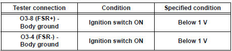
3 CHECK OCCUPANT CLASSIFICATION ECU CIRCUIT (SHORT TO B+)
- Disconnect the connectors from the occupant classification ECU and the center airbag sensor assembly.
- Connect the negative (-) terminal cable to the battery.
- Turn the ignition switch to the ON position.
- Measure the voltage according to the value(s) in the table below.
Standard voltage
4 CHECK OCCUPANT CLASSIFICATION ECU CIRCUIT (OPEN)
- Turn the ignition switch to the LOCK position.
- Disconnect the negative (-) terminal cable from the battery, and wait for at least 90 seconds.
- w/ Side airbag:
Using a service wire, connect A22-1 (FSR+) and A22-2
(FSR-) of connector "B".
NOTICE: Do not forcibly insert a service wire into the terminals of the connector when connecting.
- w/o Side airbag:
Using a service wire, connect A22-3 (FSR+) and A22-10
(FSR-) of connector "B".
NOTICE: Do not forcibly insert a service wire into the terminals of the connector when connecting.
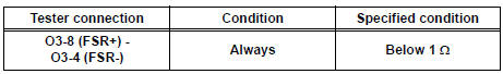
- Measure the resistance according to the value(s) in the table below.
Standard resistance
5 CHECK OCCUPANT CLASSIFICATION ECU CIRCUIT (SHORT)
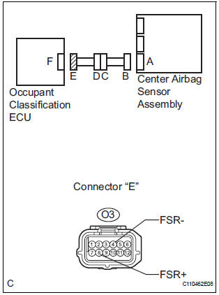
- Disconnect the service wire from connector "B".
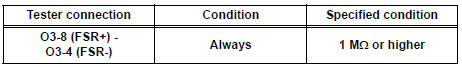
- Measure the resistance according to the value(s) in the table below.
Standard resistance
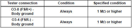
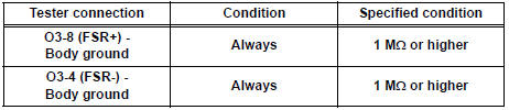
6 CHECK OCCUPANT CLASSIFICATION ECU CIRCUIT (SHORT TO GROUND)
- Measure the resistance according to the value(s) in the table below.
Standard resistance
7 CHECK DTC
- Connect the connectors to the occupant classification ECU and the center airbag sensor assembly.
- Connect the negative (-) terminal cable to the battery.
- Turn the ignition switch to the ON position.
- Clear the DTCs stored in the memory.
HINT: First clear DTCs stored in the occupant classification ECU and then in the center airbag sensor assembly.
- Turn the ignition switch to the LOCK position.
- Turn the ignition switch to the ON position.
- Check the DTCs.
OK: DTC B1790 is not output.
HINT: Codes other than DTC B1790 may be output at this time, but they are not related to this check.
8 REPLACE OCCUPANT CLASSIFICATION ECU
- Turn the ignition switch to the LOCK position.
- Disconnect the negative (-) terminal cable from the battery, and wait for at least 90 seconds.
- Replace the occupant classification ECU.
HINT: Perform the inspection using parts from a normal vehicle if possible.
9 PERFORM ZERO POINT CALIBRATION
- Connect the negative (-) terminal cable to the battery.
- Connect the intelligent tester to the DLC3.
- Turn the ignition switch to the ON position.
- Using the intelligent tester, perform "Zero point calibration".
OK: "COMPLETED" is displayed.
10 PERFORM SENSITIVITY CHECK
- Using the intelligent tester, perform "Sensitivity check".
Standard value: 27 to 33 kg (59.52 to 72.75 lb)
11 CHECK DTC
- Turn the ignition switch to the ON position.
- Clear the DTCs stored in the memory.
HINT: First clear DTCs stored in the occupant classification ECU and then in the center airbag sensor assembly.
- Turn the ignition switch to the LOCK position.
- Turn the ignition switch to the ON position.
- Check the DTCs.
OK: DTC B1790 is not output.
HINT: Codes other than DTC B1790 may be output at this time, but they are not related to this check.
END
12 CHECK FRONT SEAT WIRE RH (SHORT TO B+)
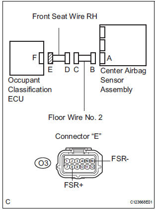
- Turn the ignition switch to the LOCK position.
- Disconnect the negative (-) terminal cable from the battery, and wait for at least 90 seconds.
- Disconnect the front seat wire RH connector from the floor wire No. 2.
- Connect the negative (-) terminal cable to the battery, and wait for at least 2 seconds.
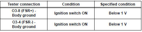
- Turn the ignition switch to the ON position.
- Measure the voltage according to the value(s) in the table below.
Standard voltage
REPAIR OR REPLACE FLOOR WIRE NO.2
13 CHECK FRONT SEAT WIRE RH (OPEN)
- Disconnect the service wire from connector "B".
- Disconnect the front seat wire RH connector from the floor wire No. 2.
- w/ Power seat:
Using a service wire, connect BO1-3 (FSR+) and BO1-5
(FSR-) of connector "D".
NOTICE: Do not forcibly insert a service wire into the terminals of the connector when connecting.
- w/o Power seat:
Using a service wire, connect BM1-3 (FSR+) and BM1-2
(FSR-) of connector "D".
NOTICE: Do not forcibly insert a service wire into the terminals of the connector when connecting.
- Measure the resistance according to the value(s) in the table below.
Standard resistance
REPAIR OR REPLACE FLOOR WIRE NO.2
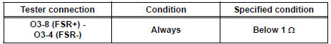
14 CHECK FRONT SEAT WIRE RH (SHORT)
- Disconnect the front seat wire RH connector from the floor wire No. 2.
- Measure the resistance according to the value(s) in the table below.
Standard resistance
REPAIR OR REPLACE FLOOR WIRE NO.2
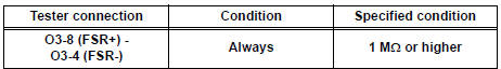
15 CHECK FRONT SEAT WIRE RH (SHORT TO GROUND)

- Disconnect the front seat wire RH connector from the floor wire No. 2.
- Measure the resistance according to the value(s) in the table below.
Standard resistance
REPAIR OR REPLACE FLOOR WIRE NO.2
 Rear Occupant Classification Sensor RH Collision
Detection
Rear Occupant Classification Sensor RH Collision
Detection
DTC B1788 Rear Occupant Classification Sensor RH Collision
Detection
DESCRIPTION
DTC B1788 is output when the occupant classification ECU receives a collision
detection signal sent by
the rear o ...
 Occupant Classification Sensor Power Supply
Circuit Malfunction
Occupant Classification Sensor Power Supply
Circuit Malfunction
DTC B1793 Occupant Classification Sensor Power Supply
Circuit Malfunction
DESCRIPTION
The occupant classification sensor power supply circuit consists of the
occupant classification ECU and
the ...
Other materials:
Towing with a wheel-lift type truck
From the front (2WD models)
Release the parking brake.
From the front (AWD models)
Use a towing dolly under the rear
wheels.
From the rear
Use a towing dolly under the front
wheels. ...
Adjustment procedure
Manual seat
Seat position adjustment lever
Seatback angle adjustment lever
Vertical height adjustment lever (driver’s side only)
Lumbar support adjustment switch (driver’s side only)*
*: If equipped
Power seat
Seat position adjustment switch
Seatback angle a ...
Disassembly
1. REMOVE RH SEAT REAR SEAT RECLINING COVER
Remove the 2 screws.
Remove the RH seat rear seat reclining cover by
pulling it out in the arrow mark direction shown in
the illustration.
2. REMOVE LH SEAT REAR SEAT RECLINING COVER
Remove the 2 screws.
R ...